
TECHNICAL SPECIFICATION
40 m Electric Telescopic Mast
with Accessory Kit
Specification, accessories, operation and maintenance manual
October 2026
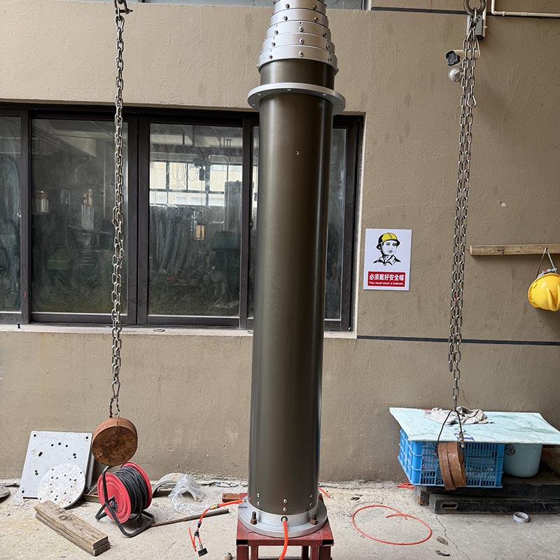
The SPM series 40 m electric locking spindle telescopic mast is a high-precision electric telescopic mast developed by Tianhemast Ltd. It is driven by a spindle screw and a locking mechanism on the connecting sleeve, which extend the mast section by section, and it is self-locking at any height.
The control system monitors the number of motor revolutions through sensors, so the extended height can be set far more accurately than with a pneumatic mast or a rope-driven mechanical mast. Four-sided keyway tubing is used to obtain better directional stability. If no mains power is available, the mast can still be operated with the manual crank handle.
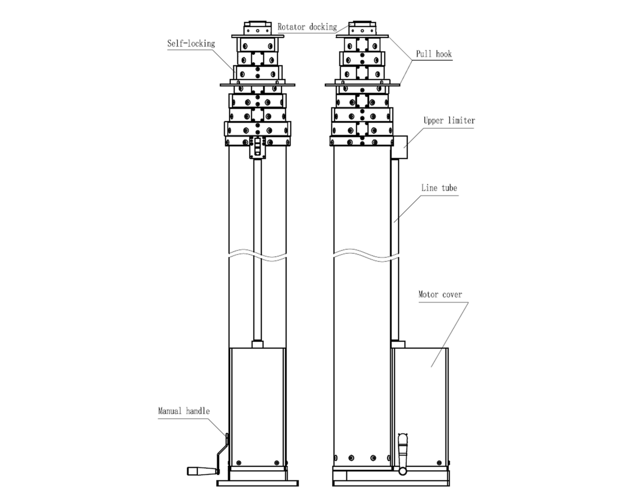
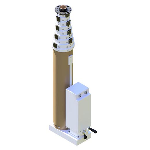
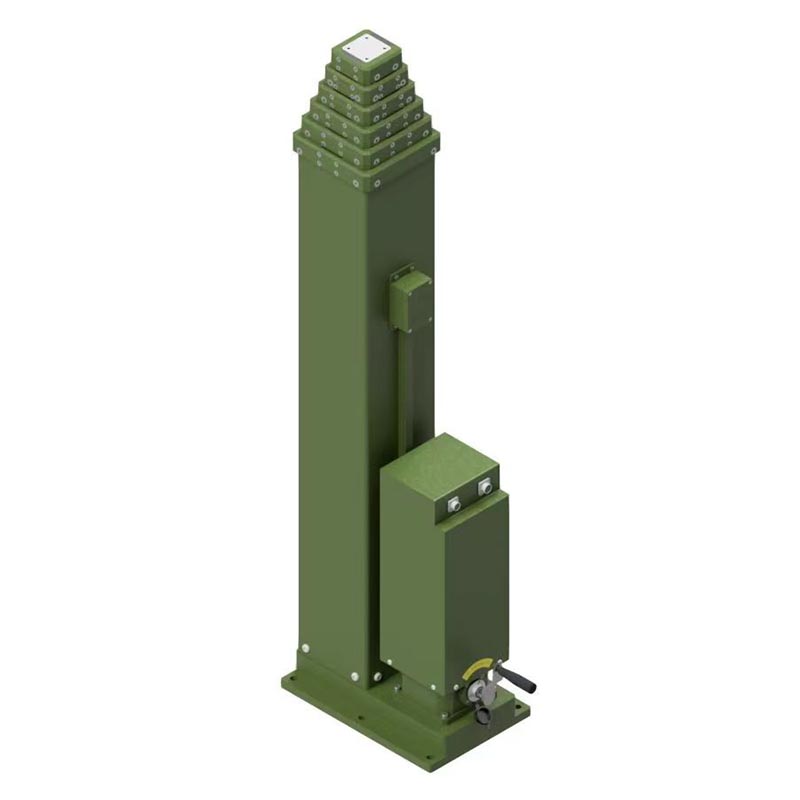
Figure 1 Mast assembly and component identification.
TABLE 1 · TECHNICAL PARAMETERS
|
PARAMETER |
SPECIFICATION |
|---|---|
|
Type of mast |
Electro-mechanical, SPM type |
|
Retracted height |
40 m |
|
Nested height |
4.9 m |
|
Number of rod body segments |
12 |
|
Rod material |
6063 aluminium alloy |
|
Minimum tube diameter |
57 mm |
|
Maximum tube diameter |
248 mm |
|
Payload |
50 kg |
|
Raising and lowering without payload |
Yes |
|
Operational wind speed |
90 km/h |
|
Maximum wind speed |
120 km/h |
|
Mounting holders (rings) for cables on each section |
Yes |
|
Working mode |
Electro / manual |
|
Power |
220 V AC / 48 V DC |
|
Power consumption |
2 kW |
|
Power cable |
3 m length |
|
Working temperature |
−40 … +60 °C |
|
Mast weight |
Approx. 440 kg |
|
Exposure to rain |
Yes |
|
Exposure to condensed precipitation (frost, dew) |
Yes |
|
Transportation |
Rail, water and air transport |
|
Hand control unit |
3 m length |
|
Russian language |
On the mast body, hand controller and transport package |
|
Colour of mast |
Black / military green |
|
Packing kit |
Mast; hand controller unit IP66 with operating temperature −40 … +60 °C; manual crank unit; hand controller cable; bracket for mast; 3 × guy ropes and tension kit; rings for cable if necessary; power cable 3 m; transport packing |
|
Warranty |
1 year |
The general arrangement of the mast — base, twelve sections and head platform — is shown below. Dimensions are in millimetres.
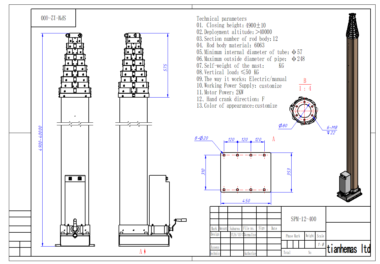
Figure 2 General arrangement drawing, SPM-12-400.
Each section is pushed up by a spindle screw running inside it and is held by a pin between sections. The drive assembly consists of the motor and reducer kit, the brass couplings and the gear box at the base of the mast.
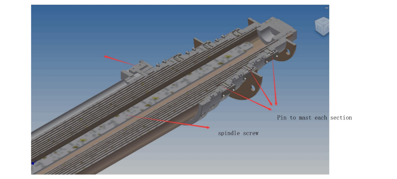
Figure 3 Mast section structure: spindle screw and inter-section pin.
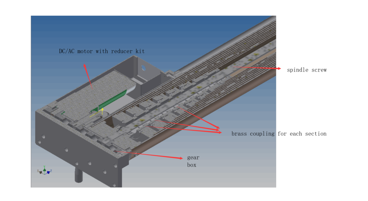
Figure 4 Drive assembly: motor and reducer kit, brass couplings and gear box.
The mast is guyed at three levels, in three directions. The ropes are attached to the mast sleeves and anchored to the ground at 23 m from the base, as shown in the layout below.
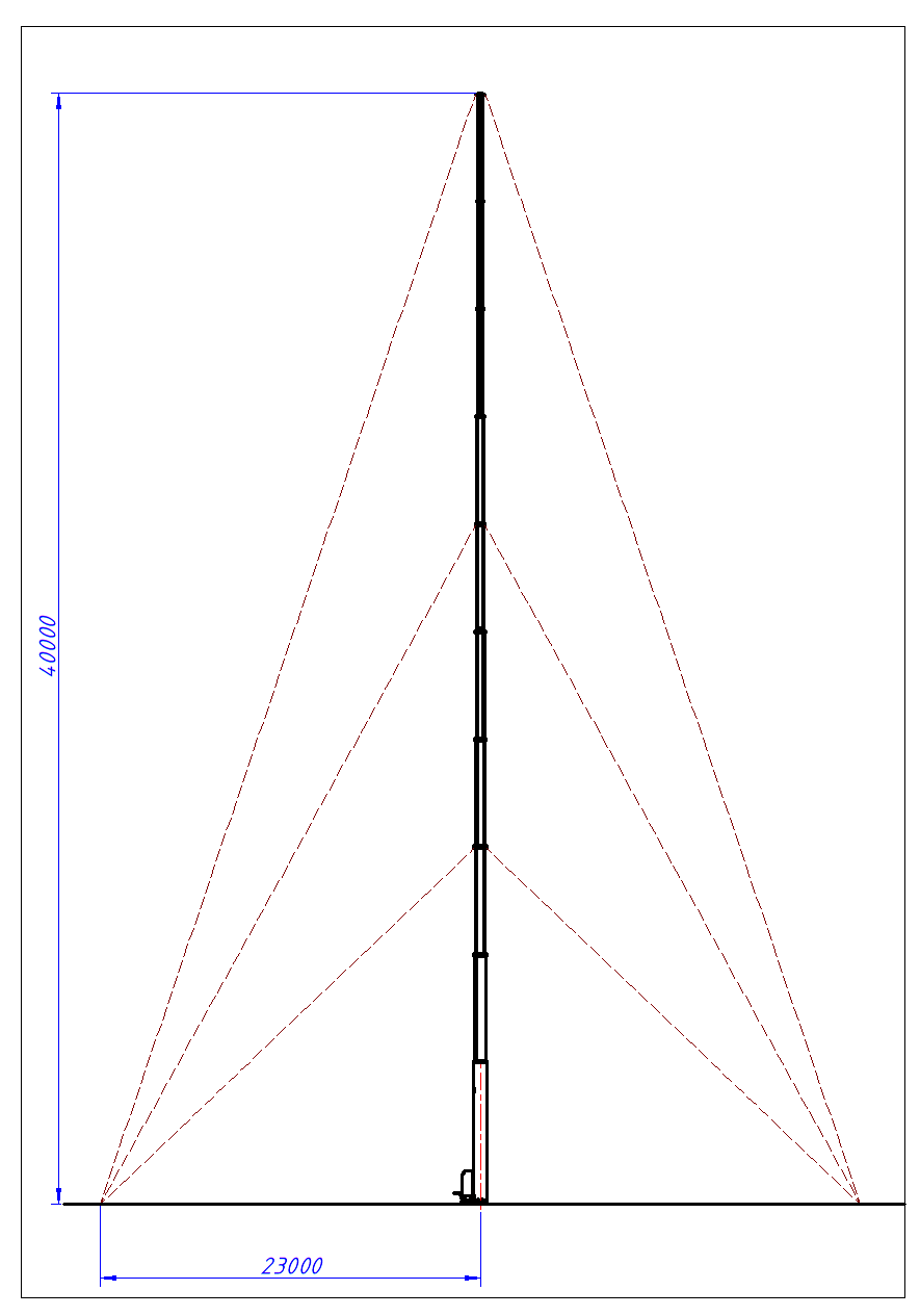
Figure 5 Guy rope application layout.
TABLE 2 · OPERATING SEQUENCE
|
STEP |
OPERATION |
|---|---|
|
01 |
Before using the mast, the mast should be installed upright on the base and screwed to the mounting holes of the solid chassis, whether it is a vehicle or the ground. Adjust the mast vertically so that it is perpendicular to the horizontal plane; the mast should have no angle against the gravity centre line. |
|
02 |
Make sure that the load objects (rotator and antenna) are securely fastened or bolted to the mast top section platform, so that they cannot fall and cause major injury. |
|
03 |
Before raising the mast, attach the guy ropes to each stage of the mast where a hook is provided; at the same time unlock the tension kit and drive it into the ground 23 m from the mast base. |
|
04 |
Elevate the mast section by section until it reaches the full height. |
|
05 |
Adjust the tension kits with the proper force and check from a distance whether the mast is straight on the gravity centre line, then lock the tension kits. |
The mast maintenance cycle is 3 to 4 months. Maintenance items:
▪ Check the mast for damaging cracks or other defects.
▪ Check whether the screws of each component are loose; if so, tighten them again.
▪ Check whether the functions of the mast are working normally.
1. The mast must strictly follow the maintenance items according to the maintenance cycle, and the relevant records must be kept.
2. Before using the mast, check whether the area directly above the mast is clear and ensure that there are no obstacles (such as power grids or buildings) within the mast's travel range.
3. During the mast raising and lowering process, it is strictly forbidden to stand within a 5-metre radius around the mast.
4. When the mast is used in rain, the motor part must be fully waterproofed and the drainage outlet at the bottom of the mast must be kept unobstructed, so that rainwater is discharged in time and does not accumulate inside the mast and damage electronic components.
5. In strong winds the mast must be secured with guy ropes, so that the lateral wind force cannot exceed the mast's wind resistance limit.
6. If any abnormal noise or jamming is found during raising or lowering, stop using the mast immediately and resume operation only after the fault has been cleared by professionals.
7. When the mast is mounted on a vehicle, a support leg levelling system should be installed on the vehicle. Before operating the mast, level the vehicle compartment through the levelling system and keep the mast as vertical as possible.
8. Mast maintenance and repair must be carried out by professionally trained personnel. The power supply must be disconnected before the mast is disassembled, to prevent the risk of electric shock. Damaged parts must be replaced with original parts.
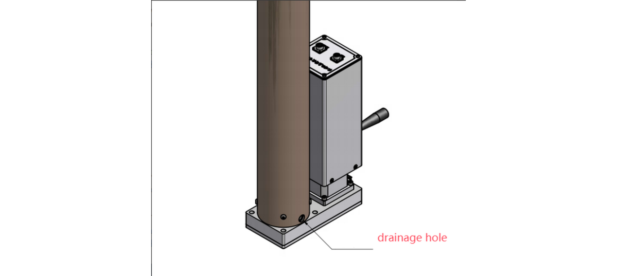
Figure 6 Drainage hole at the bottom of the mast.
TABLE 3 · TROUBLE SHOOTING
|
PROBLEM |
DIAGNOSE |
SOLVE |
|---|---|---|
|
Mast does not work |
Check whether the working power supply is connected correctly |
Connect to the working power supply correctly |
|
Check the connection between the remote control handle and the mast |
Connect the remote control handle to the mast correctly and lock it |
|
|
Check whether the motor is overheating |
Wait for the motor temperature to drop to normal temperature |
|
|
Check whether the circuit connectors are loose |
Reconnect and tighten the loose joints |
|
|
Check whether the fuse is burnt out |
Replace the fuse |
1. For long-distance transportation the mast must be packed and placed in wooden or other boxes for protection.
2. It is strictly forbidden to stack heavy objects on the mast, to prevent the mast cylinder from twisting and deforming.
3. When the mast is not in use for a long time, it must be packed and stored upright to prevent damp. The mast must not be stored horizontally for a long time, to prevent the internal transmission screw from bending and deforming.
1. The mast must be used vertically. It is prohibited to use the mast horizontally or inverted.
2. The vertical installation angle of the mast should be less than 5° from the horizontal plane.
3. The load must be carried according to the payload indicated in the technical parameters of the mast; overloading is prohibited.
4. It is prohibited to use the mast as a lightning rod.
5. The mast is only used for lifting equipment and is strictly prohibited as a means of carrying people.
6. When the mast is installed on a vehicle, it must be restored to the closed state before driving.
7. It is strictly forbidden to drill, weld or otherwise reprocess the outside of the mast sections.
8. It is strictly forbidden to remove any screw from the mast body.
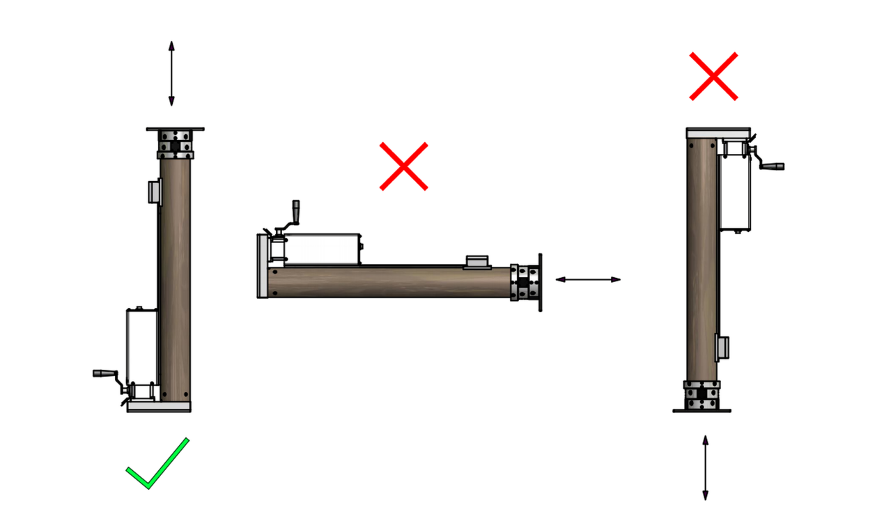
Figure 7 Permitted and prohibited installation orientations.
During periods of heavy precipitation and high ice build-up on the mast there is a chance of jamming while a deployed mast is retracted. Ice build-up on the collar sections (horizontal surfaces) of the mast can cause the tube lock mechanisms to become "out of time" and cause internal damage. This ice must be cleared away during retraction, just before the individual tubes and collars contact each other.
Wear gloves when handling the ice breakers to avoid being cut. The order of operations for ice removal is as follows:
Note: only retract the mast with electrical power; do not attempt to use the manual crank input. Internal damage may occur if the manual crank is used during high-torque applications.
TABLE 4 · ICE REMOVAL PROCEDURE
|
STEP |
ACTION |
|---|---|
|
1 |
Attempt to retract the mast with electrical power only. If the mast begins to break the ice on its own, proceed to Step 4. If the mast stalls and does not retract, proceed to Step 2. Do not continue to labour the motor with a stalled tube set, as this will wear the slip clutch. |
|
2 |
Begin clearing the ice on the horizontal surfaces (collar) closest to the operator. Using non-piercing tools, break the ice bond with a striking motion away from the tube (tangent to the tube). Continue around the collar, then remove the remaining ice from the vertical lock post on the collar and start removing the ice build-up on the nesting tube. Use extreme caution on the circumference of the tube — only 1–2 vertical inches of ice need to be removed; use a tangential clearing motion so the tube is not pierced. Proceed to Step 3. |
|
3 |
Once again, attempt to retract the mast electrically. If the tube set is still stalled, ice has built up internally and the unit will need to be thawed before it can function again. Do not continue to labour the motor with a stalled tube set; save the slip clutch. If the mast does retract, proceed to Step 4. |
|
4 |
Continue to retract the tube until it is a few inches from nesting and contacting the lower collar. Clear away the ice on the horizontal surfaces (collar) closest to the operator as described in Step 2, then operate the mast until the collars contact and the next tube begins to retract. At this point repeat Steps 1 and 4. |
|
5 |
If the mast continues to break ice during retraction but has trouble only near a locking transition, ice has frozen inside the lock body and is interfering with normal unlocking. Use a small, hard tool to reach inside the opening at the bottom of the housing, chip and clear the ice from the internal parts, then set the latch to the proper "Locked" orientation as illustrated in Figure 9. Attempt to retract the mast again under electrical power. Using non-piercing tools, remove the ice build-up from the indicated areas. |
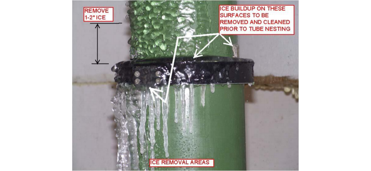
Figure 8 Ice removal areas.
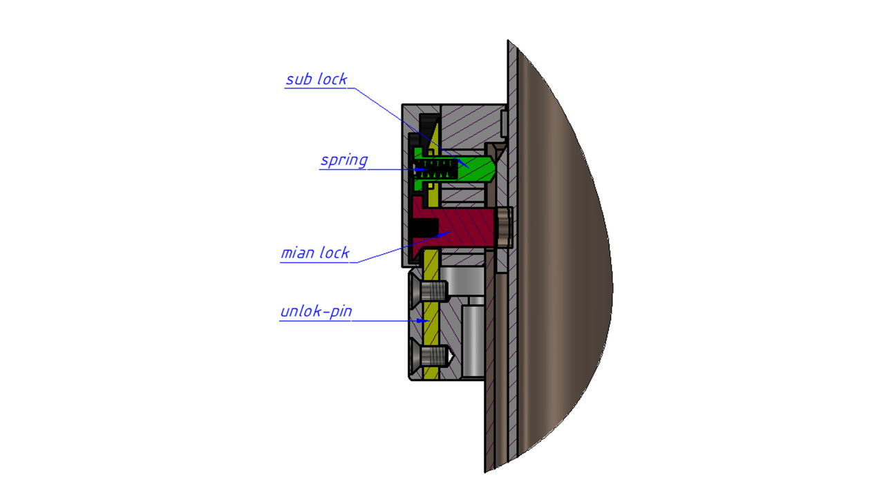
Figure 9 Lock body section: sub lock, spring, main lock and unlock pin.
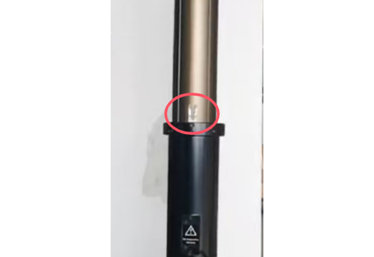
Figure 10 Location of the unlock pin, marked in red.
Make sure there is no ice on the unlock pin before any powered operation is carried out. The red circle marks the location of the unlock pin.
The mast section and its control system were tested in a constant-temperature and humidity chamber down to −40 °C, the lower limit of the specified working temperature range.
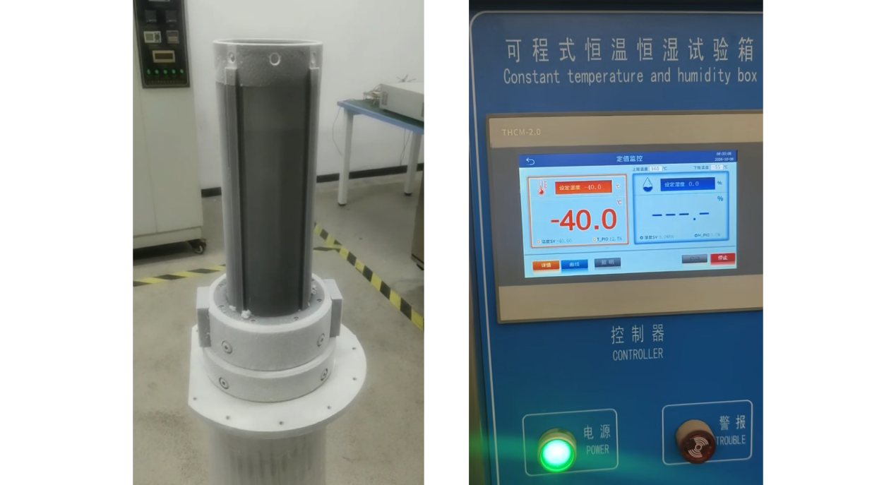
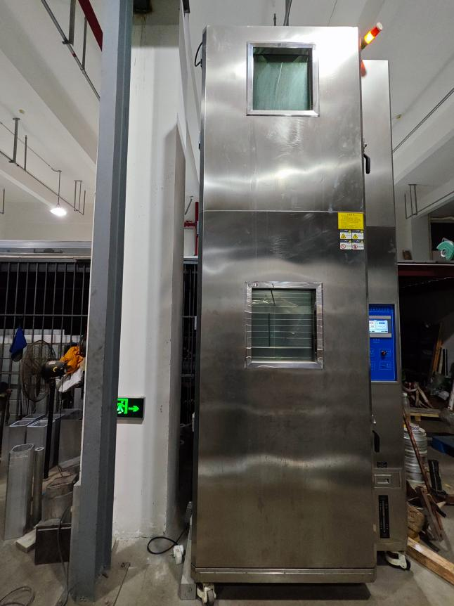
Figure 11 Low-temperature test at −40 °C: chamber view and controller reading.
Chapters 8 to 13 describe the accessory kit supplied with the 40 m mast, its configuration and its operating instructions.
The wind safety protection system monitors wind speed at the mast head. When the measured wind speed exceeds a preset threshold — the value to be decided by the client — the controller signals the PLC, which lowers the mast automatically.
TABLE 5 · WIND SENSOR SPECIFICATIONS
|
PARAMETER |
ITEM |
SPECIFICATION |
|---|---|---|
|
DC power supply (default) |
10–30 V DC |
|
|
Power consumption |
0.12 W |
|
|
Measuring range |
Wind speed |
0–40 m/s (customizable) |
|
Wind direction |
0–360° |
|
|
Accuracy |
Wind speed |
±(0.5 + 2% FS), 0–30 m/s, 60% RH, 25 °C |
|
Wind direction |
±3°, 60% RH, 25 °C |
|
|
Resolution |
Wind speed |
0.01 m/s |
|
Wind direction |
1° |
|
|
Operating environment |
−40 to 80 °C; 0–95% RH (non-condensing) |
|
|
Wind resistance |
75 m/s |
|
|
Response time |
1 s |
|
|
Protection rating |
IP65 |
|
|
Output signal |
RS-485 (Modbus-RTU protocol) |
|
Note: FS = full scale; RH = relative humidity. The measuring range can be customized on request.
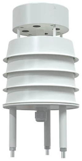
Figure 12 Wind speed and direction sensor.
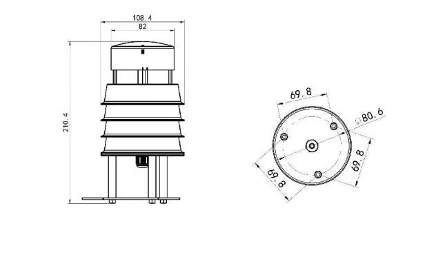
Figure 13 Weather sensor dimensions.
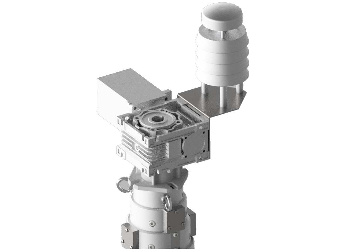
Figure 14 Weather sensor mounting on the mast head.
All cables are run inside a braided mesh sleeve for mechanical protection while the mast extends and retracts.
▪ CAT6 + 2 × 1.0 mm² — client antenna signal and power
▪ 4 × 1.0 mm² — rotator power and control
▪ 2 × 1.0 mm² — weather sensor signal; power may be taken from the client antenna supply, since the sensor draws very little current
The sleeve is fixed at the mast head and at the base and takes up the change in cable length as the mast moves, so that no cable is left loose in the wind.
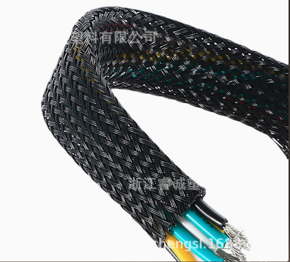
Figure 15 Cables bundled in the braided mesh sleeve.
The cable is stored on a hand-operated drum. While the mast rises, the cable follows it without any power being required; when the mast is lowered, the cable is wound back onto the drum by hand.
1. When the mast is going up, the cable follows the mast upwards together with it, without any power needed.
2. When the mast is going down, the cable piles up randomly on the ground.
3. The cable is then stored manually into the cable drum with the hand winch.
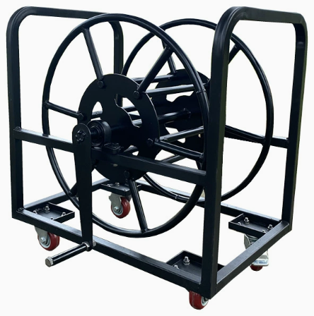
Figure 16 Cable drum on castors for cable take-up and storage.
As an alternative to the manual drum, a spring-driven retractable cable reel can be supplied. It is designed for PTZ cameras and antenna masts: a rugged steel housing, a self-rewinding cable with ratchet lock and a bolt-on swivel base give quick, tidy cable management in the field.
▪ Purpose-built for PTZ camera and antenna mast power and signal cable
▪ Self-retracting spring mechanism with multi-position ratchet lock
▪ Heavy-gauge steel housing with weather-resistant olive-drab finish
▪ 360° swivel mounting base, bolted directly onto masts, poles and vehicle racks
▪ Reinforced strain relief and impact-resistant cable guide
▪ Pull-out handle for fast, one-handed deployment
TABLE 6 · RETRACTABLE CABLE REEL SPECIFICATIONS
|
PARAMETER |
SPECIFICATION |
|---|---|
|
Cable length |
30 m (other lengths on request) |
|
Cable type |
CAT6 + 2 × 1.0 mm² for antenna signal and power; 4 × 1.0 mm² for rotator power and control; 2 × 1.0 mm² for weather sensor signal |
|
Connector |
IP66 waterproof socket |
|
Housing |
Cold-rolled steel, powder-coated |
|
Mounting |
Bolt-on base plate, 360° swivel |
|
Cable take-up |
Spring-loaded, self-retracting with multi-position ratchet lock |
|
Operating temperature |
−40 °C to +60 °C |
Note: the cable follows the mast upwards without power and is taken up by the internal spring when the mast is lowered. Applications: PTZ surveillance, mobile antenna masts, temporary field deployments and vehicle-mounted communications.
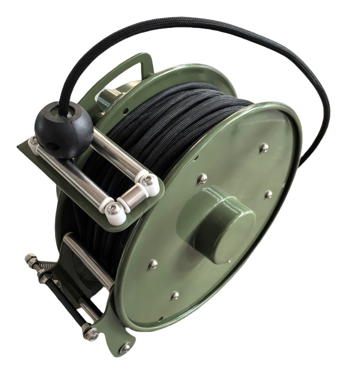
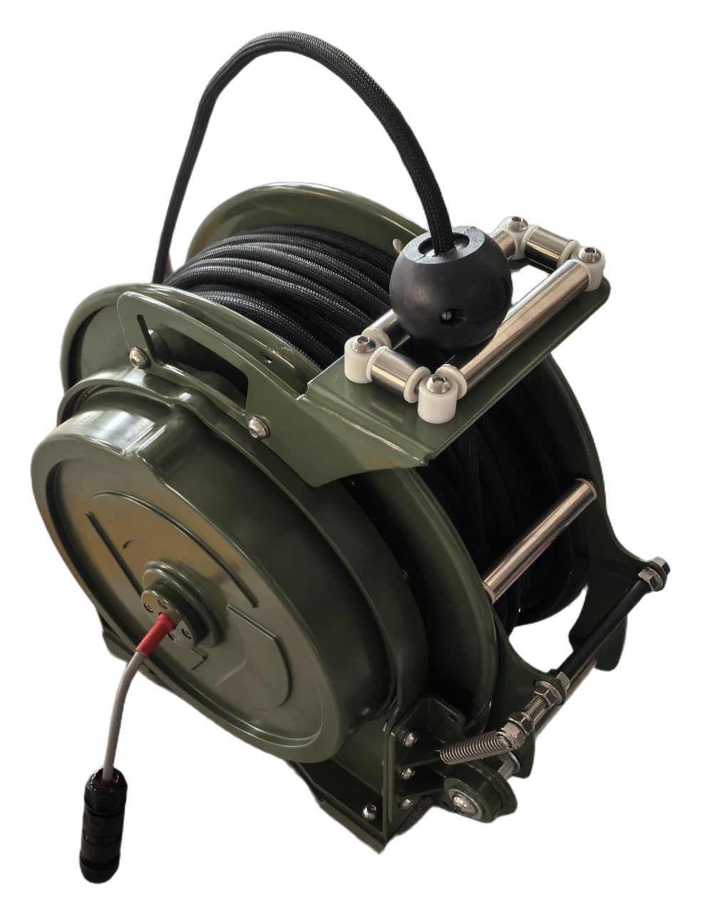
Figure 17 Retractable cable reel, oblique and front view.
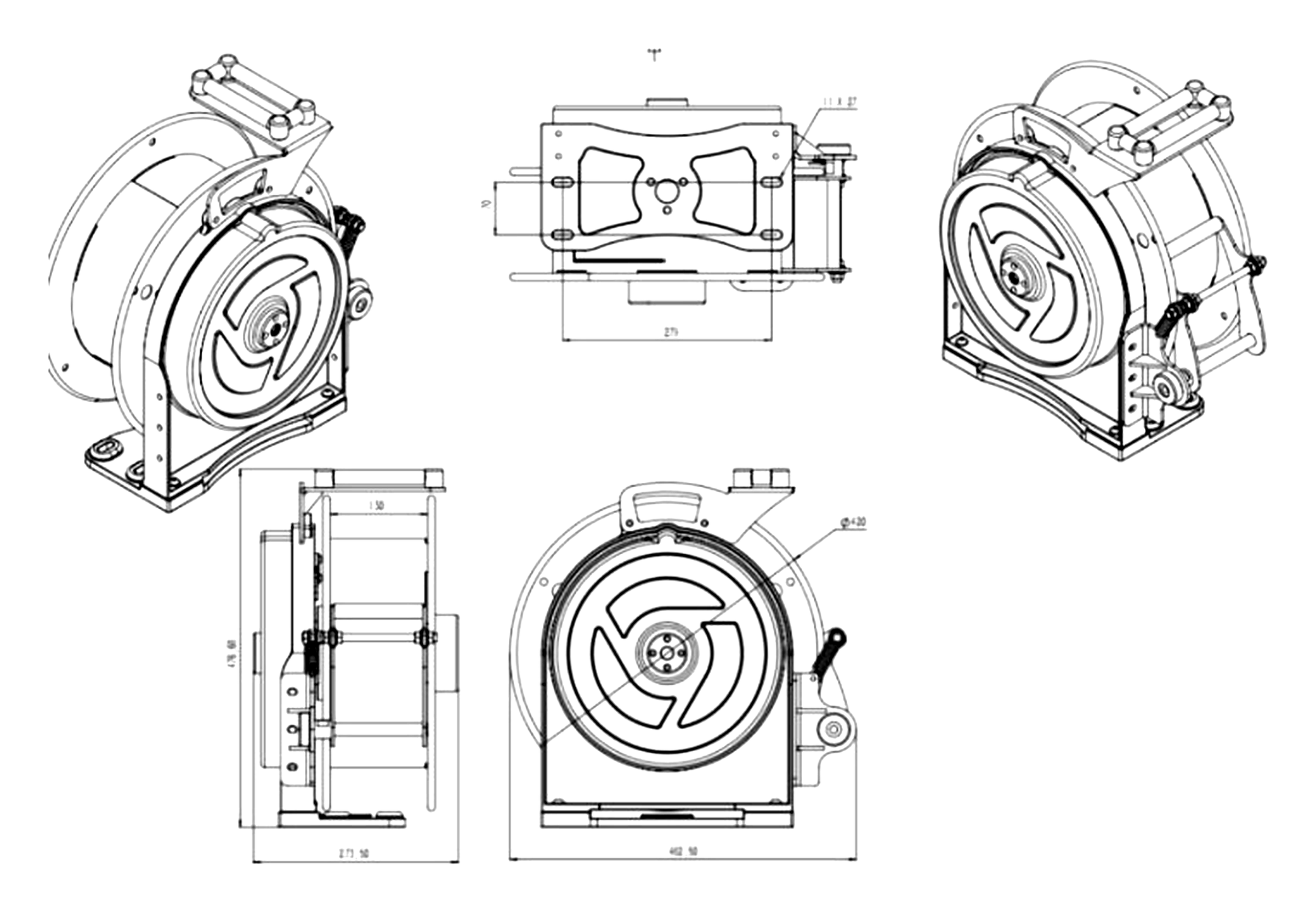
Figure 18 Cable reel: general arrangement drawing, dimensions in mm.
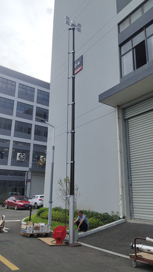
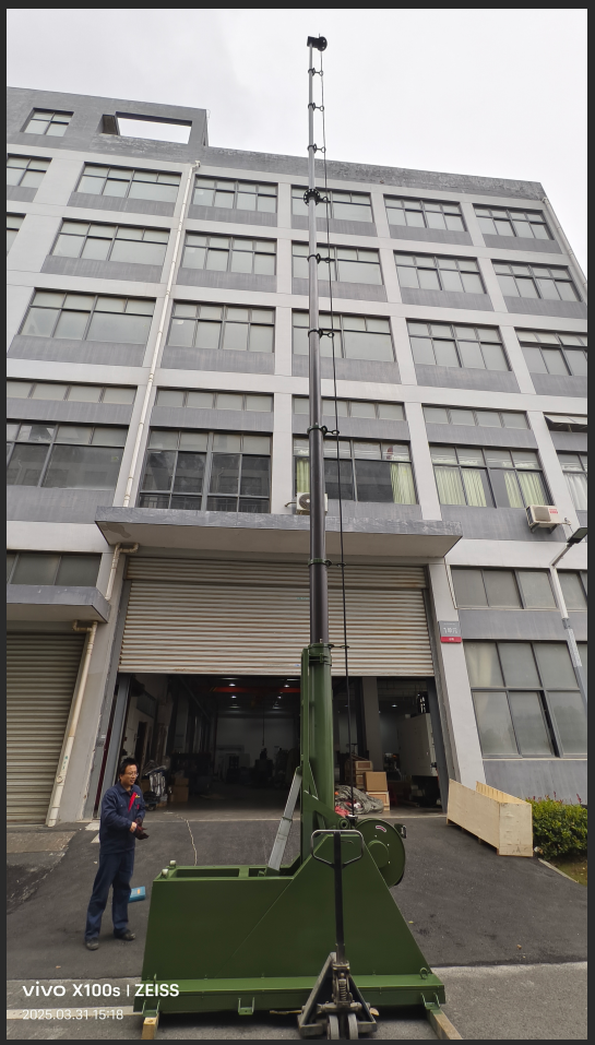
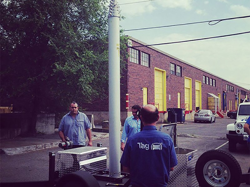
Figure 19 Mast erected for field deployment, with the cable reel at the base. A hook on every mast sleeve carries the cable clear of the sections and keeps it from swinging in the wind.
The Sky40HP antenna positioner turns the mast head assembly. Rated figures for this model are: rotating torque 140 N·m, maximum torque 240 N·m, breaking torque 1,500 N·m, permissible wind area 2 m², rotation range 360° ± 70° and minimum rotation time 70 s.
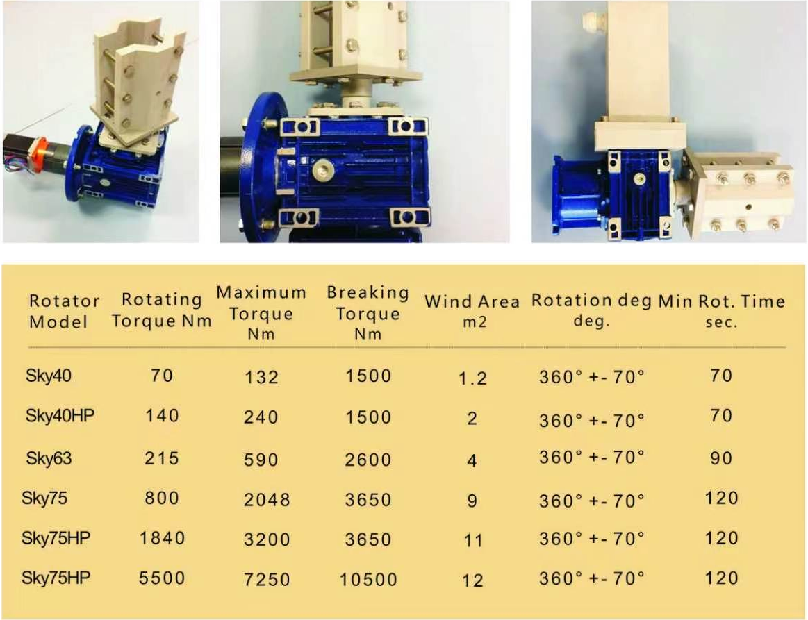
Figure 20 Antenna positioner range: product views and rated performance; the Sky40HP is the second model listed.
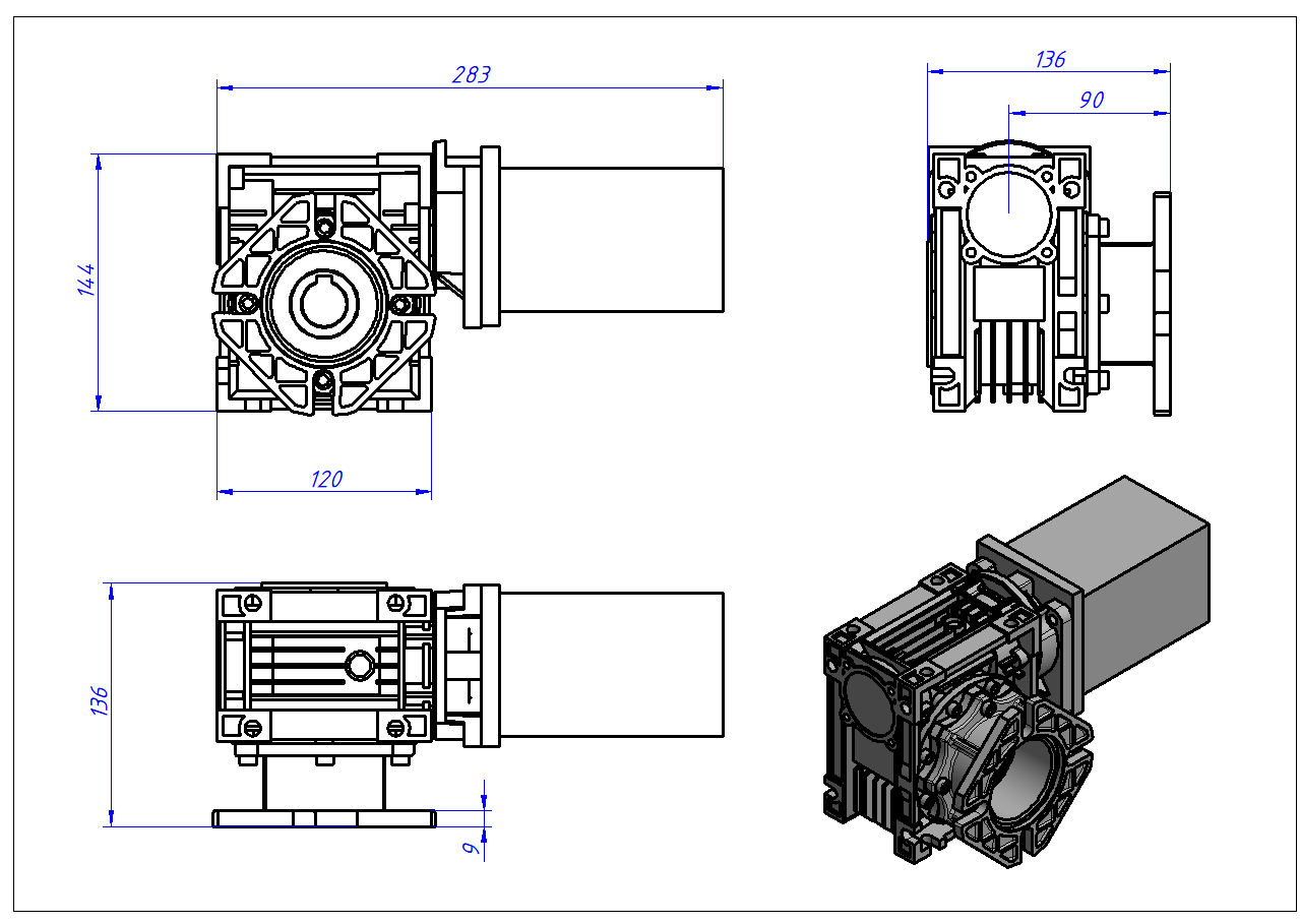
Figure 21 Sky40HP rotator outline dimensions (mm).
The mast is guyed at three levels, in three directions, using stainless steel rope and adjustable tension kits.
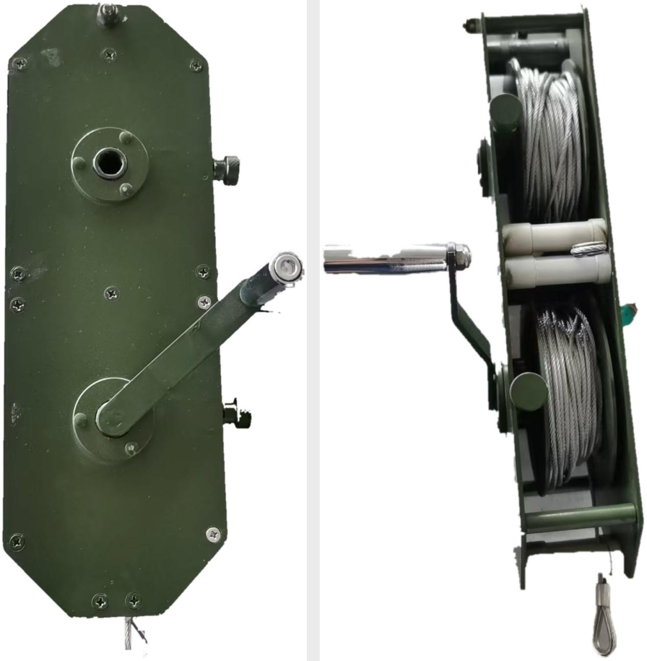
Figure 22 Guy rope tension kit with hand winch: rope spools, guide rollers and wire rope thimble, front and side view.
1. Before the mast extends, unlock the tension kit and hook the three stainless steel rope hooks onto the mast sleeves at the three attachment points.
2. At 23 m, drive the ground nail to anchor the tension kit.
3. As the mast elevates, the stainless steel guy ropes follow the mast without power.
4. When the mast reaches full height, adjust the guy ropes to the proper tension and lock the tension kit.
▪ Ground nail: 16 mm OD, 650 mm long.
▪ The rotary hammer shown is for reference only; any equivalent model is acceptable.
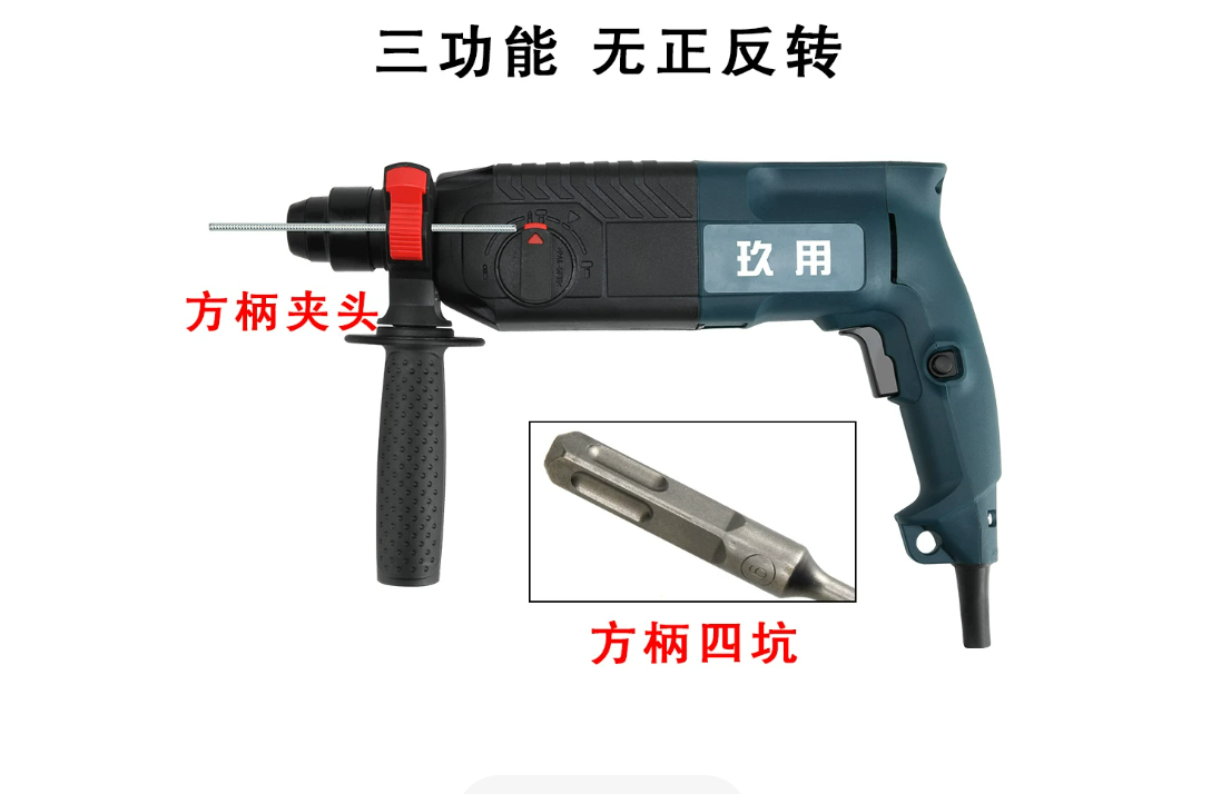
Figure 23 Rotary hammer used to drive the ground nail (reference photo).