
HOMALL INDUSTRY
TELECOMMUNICATION TOWER SYSTEMS
45 m Telescopic Lattice Tower
General Specification & Operation Manual
Document No. HI-TMS147-SM-01 Revision 1.0 Issue November 2026
Prepared by Homall Industry Status Issued for customer review
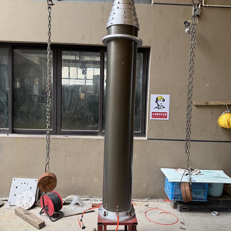
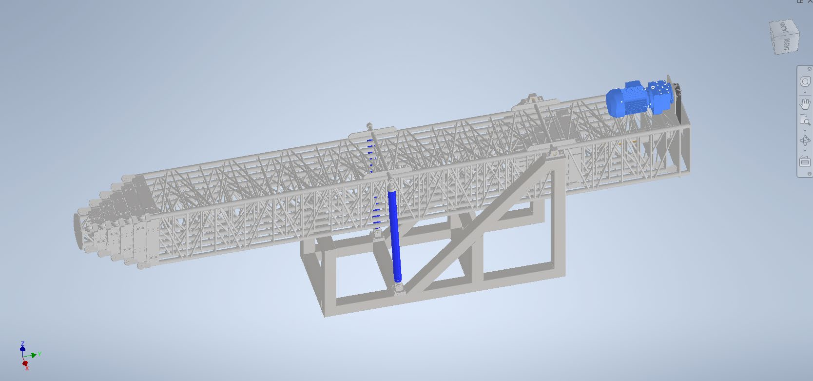
The Homall TMS-147 is a self-supporting (subject to the load and environmental conditions stated in this document) and guy-capable telescopic tower with an extended height of approximately 45 m (147 ft) above ground level (AGL). The structure comprises six 9 m heavy-duty, hot-dip galvanized steel telescoping lattice sections mounted on a structural base incorporating a 90° tilting mechanism.
The tower is tilted to the vertical position by tandem heavy-duty hydraulic cylinders and is then elevated automatically by a spindle drive through a 22 kW motorized belt-and-gear system. As the sections extend one by one, each section locks automatically by means of four-way latch pins; every latch pin carries a maximum load of 6 t, giving a combined capacity of 12 t for the complete system.
To ensure the safety of tower operation, several limit switches are integrated into the system. When the mast reaches its full height, an upper limit switch automatically disconnects the motor circuit. In addition, should a limit switch fail, the spindle will rotate freely without engaging the screw nut mounted at the bottom of each tower section, so that over-travel cannot occur.
The principal design advantage is the spindle-screw elevation system developed by Homall Industry, which eliminates the stainless-steel rope, pulley and redundant rope arrangements used by conventional telescopic towers. The result is safer and simpler operation, and a substantial reduction in maintenance effort and downtime.
The following equipment is supplied with the TMS-147 tower system. Items marked optional are quoted separately and do not form part of the standard scope of supply.
|
No. |
Item |
Scope |
|---|---|---|
|
1 |
45 m telescopic tower, six 9 m lattice sections, hot-dip galvanized |
Standard |
|
2 |
Hydraulic power unit and multi-section oil cylinder |
Standard |
|
3 |
PLC control system |
Standard |
|
4 |
Touch-screen operator panel |
Standard |
|
5 |
Lightning protection kit |
Standard |
|
6 |
Aviation obstruction LED light, solar powered |
Standard |
|
7 |
Drive motor, 22 kW, three-phase |
Standard |
|
8 |
Kevlar guy-rope kit |
Optional |
The trailer is not part of the scope of supply. The interface between trailer and tower is defined in Section 9.3.
Sections are numbered from the top of the tower (Section 6) to the base (Section 1).
|
Section |
Face width |
Length |
Leg tube OD / wall |
Diagonal brace / rod |
Approx. mass |
|---|---|---|---|---|---|
|
6 (top) |
0.40 m |
9 m |
80 mm / 3 mm |
30 mm / 3 mm |
411 kg |
|
5 |
0.54 m |
9 m |
80 mm / 3 mm |
30 mm / 3 mm |
535 kg |
|
4 |
0.68 m |
9 m |
80 mm / 3 mm |
30 mm / 3 mm |
615 kg |
|
3 |
0.82 m |
9 m |
80 mm / 3 mm |
30 mm / 3 mm |
732 kg |
|
2 |
0.96 m |
9 m |
80 mm / 4 mm |
30 mm / 3 mm |
1,000 kg |
|
1 (base) |
1.10 m |
9 m |
80 mm / 4 mm |
30 mm / 3 mm |
1,614 kg |
|
Total |
|
|
|
|
4,907 kg |
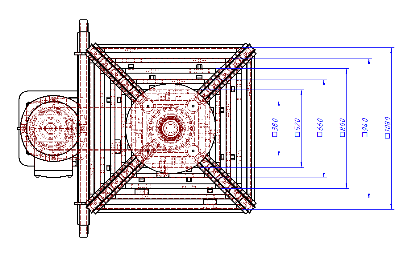
Figure 3-1 Section plan and taper of the lattice body (dimensions in mm)
|
Parameter |
Value |
|---|---|
|
Tower height, extended |
45 m (147 ft) |
|
Tower height, retracted |
10 m |
|
Number of sections |
6, each 9 m |
|
Face width, base section |
1.10 m |
|
Face width, top section |
0.40 m |
|
Payload at top of tower |
2.5 t |
|
Maximum wind speed at erection |
32 km/h |
|
Erection / retraction speed |
3.3 m/min |
|
Hydraulic tilt speed |
0° to 90° within 60 s |
|
Tilt angle |
90° |
|
Power requirement, total system |
30 kW |
|
Drive motor rating |
22 kW, three-phase asynchronous, 380 V |
|
Gear box ratio |
1 : 6.84 |
|
Motor speed |
1,400 r/min input, 213 r/min output |
|
Section locking |
Four-way latch pins, 6 t each, 12 t total |
|
Surface finish |
Hot-dip galvanized to ASTM A-123 |
Wind speed ratings are derived from prior structural studies only. Actual ratings may vary significantly with the client-specific load case and are to be confirmed by the project analysis described in Section 5.
|
Component |
Specification |
|---|---|
|
Legs, mechanical tubing, welded |
HSS ASTM DOM 1026 alloy |
|
Structural shapes: solid rod, bars, angle |
ASTM A-36, 36 ksi yield strength |
|
Structural steel tube |
ASTM A-500, 50 ksi yield strength |
|
Welding electrode |
E70, AWS D1.1 latest revision |
|
Hot-dip galvanizing |
ASTM A-123 |
|
Bolts and hardware |
ASTM F1941, SAE Grade 8 |
|
Horizontals, flat bar |
ASTM A-36, 36 ksi yield strength |
Structural design: All work shall conform to the requirements of the Uniform Building Code (UBC) and to the structural requirements of the Telecommunications Industry Association / Electronic Industries Alliance, TIA/EIA-222-G.
Fabrication: Steel fabrication shall conform to the AISC Manual of Steel Construction and the applicable Electronic Industries Alliance requirements.
Workmanship: Welding to AWS D1.1; galvanizing to ASTM A-123; bolting to ASTM F1941.
The operating principle of the TMS-147 differs from that of most telescopic towers on the market, which are generally driven by a stainless-steel rope with pulleys and a redundant rope kit. Each tower section of the TMS-147 carries a special coupling at its base that embraces the spindle screw used for elevation. The spindle is connected through a belt to a gear at the base frame; on the opposite side of the belt the assembly is driven by a three-phase asynchronous motor rated at 22 kW.
Easy assembly and maintenance: Fewer components, no rope re-termination and direct access to the drive at the base frame.
Locking at any height: The tower can be held at any intermediate height by the spindle together with the motor brake, giving a double lock that prevents retraction.
Safer operation: No stainless-steel rope is used in the load path, removing the most common cause of rope wear, birdcaging and sudden failure.
Smooth elevation: The spindle drive produces smooth elevation without the shock loading associated with rope take-up.
|
Parameter |
Value |
|---|---|
|
Motor type |
Three-phase asynchronous motor |
|
Power consumption |
22 kW |
|
Voltage |
380 V |
|
Rated speed |
1,400 r/min |
|
Transmission |
Belt drive to spindle gear |
|
Gear box ratio |
1 : 6.84 |
|
Output speed at spindle |
213 r/min |
|
Brake |
Integral motor brake, spring applied |

Figure 4-1 Drive motor, 22 kW three-phase asynchronous
A rigorous finite element analysis (FEA) program, STAAD.Pro, may be used to carry out the stress analysis review and to determine tower member design in conformance with the ANSI/TIA/EIA-222-G standard requirements for a client's specific load configuration.
The latticed tower members are modeled using beam elements for the leg members, truss elements for the bracing and cable elements for the raising, lowering and support spindle. The structural parameters and geometry of every member are included in the model. Wind loading is calculated for the different wind directions and applied as external loads on the structure, with self-weight determined internally by the solver. In order to obtain the maximum stress occurring in all tower members and guy wires, where the guyed configuration is deployed, four wind directions relative to the tower and guys are considered: face wind, apex wind, parallel wind and the corresponding diagonal case.
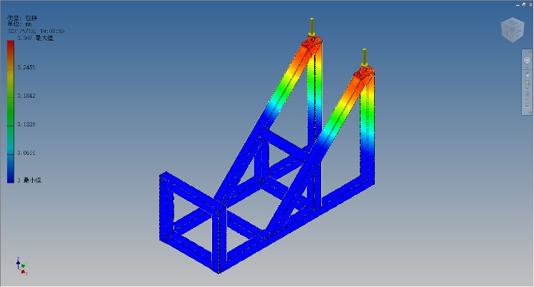
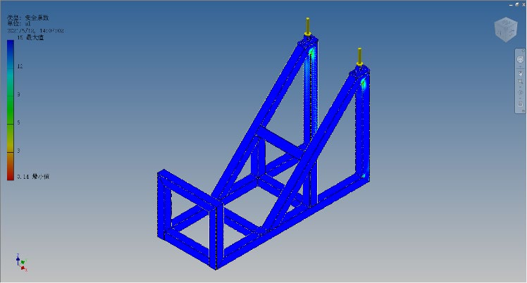
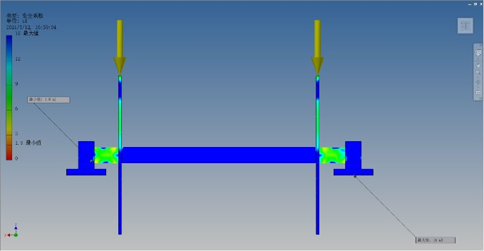
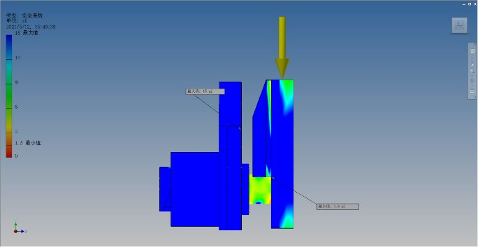
The results below are taken from the analysis of the TMS-147 in the fully erected condition. All members remain within the yield stress of the steel under the rated load case.
 |
 |
|---|
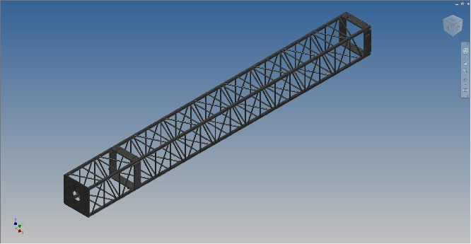
Figure 5-1 Displacement of the tilt structure under full load: maximum 0.3 mm; maximum stress within the yield stress of the steel
 |
 |
|---|
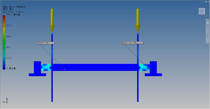
Figure 5-2 Lock pin analysis: stress distribution within the yield stress of the steel
 |
 |
|---|
Figure 5-3 Axle analysis of the tilt mechanism under full load
Given the environmental conditions in which the equipment may be deployed, Homall Industry proposes to manufacture the tower and trailer for survival and storage without excessive degradation that would render the equipment inoperable, using the following parameters as design guides.
|
Parameter |
Requirement |
|---|---|
|
Temperature, operating |
−23 °C / −9 °F ambient as standard. −35 °C / −31 °F achievable with alternate hydraulic and gear fluids, thermostatically controlled heating or equivalent heat sources, and thermal enclosures for specific components. Up to +60 °C (140 °F) at 98 % RH at 25 °C intermittent; +40 °C (104 °F) continuous duty. |
|
Temperature, storage |
−35 °C (−31 °F) to +60 °C (140 °F); relative humidity 20 % to 100 % |
|
Solar radiation |
1,100 W/m² |
|
Altitude |
Operating to 4,000 m; non-operating and storage to 12,000 m |
|
Sand and dust |
Operational in desert environment; 0.95 g/m³ with wind speeds up to 40 km/h at 3 m height. Particle size 74 µm to 1,000 µm, average 74 µm to 350 µm. |
|
Salt spray / fog |
Storage, exposure and operation during or after exposure to salt atmosphere. Requires regular preventive maintenance and a stainless-steel cable upgrade for long-term corrosion resistance in salt air. |
|
Fungus and insects |
Storage and exposure to insect and fungus conditions; use of non-nutrient materials where practical |
|
Rain |
No leakage to sensitive parts; exposure to rain rates of 5 cm/h with wind levels of 80 km/h |
|
Sun |
Exposed surfaces and materials resistant to long-term exposure; finishes, gaskets and cables rated for solar radiation of 1,100 W/m² |
|
Corrosion |
All components protected against excessive corrosion. All surfaces painted and/or chemically treated. Galvanic corrosion avoided by isolation of dissimilar metals. All galvanized members hot-dip galvanized to ASTM A-123 at the time of fabrication. |
A solar-powered LED aviation obstruction light is fitted at the top of the tower. The unit is self-contained, with an integral photovoltaic panel and battery, and requires no external power supply.
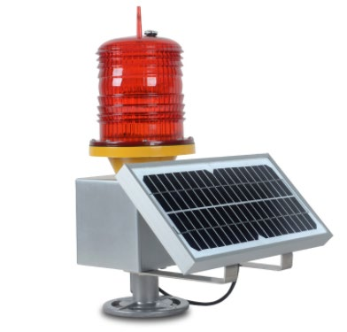 Figure 7-1 Solar-powered LED aviation obstruction light |
Parameter |
Value |
|---|---|---|
|
Type |
Aviation obstruction light, LED |
|
|
Input voltage |
18 V |
|
|
Luminous efficacy |
160 lm/W |
|
|
Material |
Aluminum, PC, ABS |
|
|
Battery |
Lead-acid, 12 V, 7 Ah |
|
|
Charging time |
6 to 8 hours |
|
|
Color temperature |
Cool white |
The lightning protection kit comprises a pre-discharge lightning arrester, a 16 mm² copper down conductor of 46 m and a copper-bonded ground rod. The arrester is of the active early-streamer type and requires no external power supply.
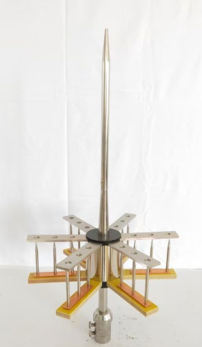 Figure 7-2 Pre-discharge lightning arrester |
Parameter |
Value |
|---|---|---|
|
Pre-discharge time |
60 µs |
|
|
Lightning impulse discharge current, Iimp |
400 kA (10/350 µs) |
|
|
Wind resistance |
40 m/s |
|
|
Material |
304 stainless steel |
|
|
Height |
600 mm |
|
|
Number of arresters |
9 |
|
|
Down conductor |
16 mm² copper cable, 46 m |
|
|
Earthing |
Copper-bonded ground rod |
Benefits of the designated arrester
New stainless material with high corrosion resistance and strong wind resistance.
Maintenance-free and passive in operation.
Long service life and simple installation.
The exciter draws energy from the cloud field and forms an upward leader, actively guiding the discharge to ground.
For the same height the protection radius is larger than that of a conventional lightning rod, reducing the probability of a strike to the protected object.
Elevation, retraction, tilting and all interlock functions are controlled from a touch-screen panel interfaced to a PLC. The controller enforces the safety interlocks described in Section 9, in particular the requirement for the safety wheel thread bolt to be fitted and sensed before elevation can be commanded.
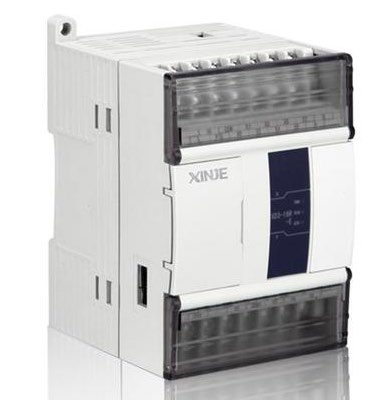 Figure 7-3 PLC control unit |
 Figure 7-4 Touch-screen operator panel |
|---|
PLC specification
XD3 series standard PLC, available in 16, 24, 32, 48 and 60 point specifications.
Complete function set, covering the requirements of the great majority of applications.
Speed and capacity substantially improved compared with the XC series.
Input type NPN; output type transistor (T) or relay (R); power supply AC 220 V.
Supports X-NET fieldbus, high-speed counting to 80 kHz, pulse output to 100 kHz and frequency measurement.
Standard USB port for program download; supports one to ten expansion modules, one expansion ED and one to two expansion BD (16-point models excluded).
|
Item |
Specification |
|---|---|
|
Insulation voltage |
Above DC 500 V, 2 MΩ |
|
Anti-noise |
Noise voltage 1,000 Vp-p, 1 µs pulse, 1 minute |
|
Atmosphere |
No corrosive or flammable gas |
|
Environmental temperature |
0 °C to 60 °C |
|
Environmental humidity |
5 % to 95 % |
|
USB |
Quick download port; connect to PC for download, upload and monitoring |
|
PORT1 |
RS232, to host computer or HMI for programming and debugging |
|
PORT2 |
RS485, to smart meters, inverters and similar devices |
|
PORT3 |
Expansion ED communication port |
|
GND (FG) |
Third type of grounding; not common grounding with the power system |
Touch-screen specification
Slim-bezel design with multiple download methods: Ethernet, USB port and USB flash drive.
Penetrating function; XD, XL and XG series PLC programs can be uploaded and downloaded through the panel.
16.77 million colors; display quality comparable with an LCD monitor.
Download, start and run in a single high-speed response.
C-language script support, free protocol writing and drawing tools; BMP and JPEG images, 3D graphics library, custom animation, data logging with time-trend and XY-trend charts, and recipe storage with two-way transfer.
|
Item |
Specification |
|---|---|
|
Size |
7 inch |
|
Resolution |
800 × 480 |
|
LCD screen |
TFT LCD, LED backlight |
|
Display color |
16.77 million colors |
|
Brightness |
200 cd/m² |
|
Touch panel |
Four-wire resistive touch screen |
|
LCD life |
More than 50,000 hours at 25 °C, 24 h operation |
|
Memory |
128 MB |
|
Anti-interference |
Interference voltage 1,500 Vp-p; pulse period 1 µs; duration 1 minute |
|
Power supply |
24 V DC |
The power unit supplies oil to the hydraulic cylinders of the tilting structure in order to raise the tower to the vertical position, and to support it while it is lowered to the horizontal position for transport.
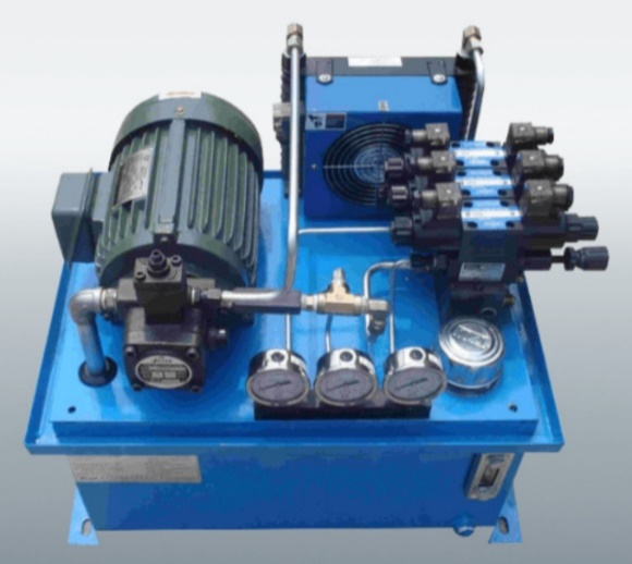 Figure 7-5 Hydraulic power unit |
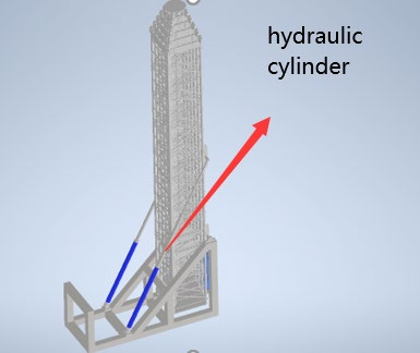 Figure 7-6 Hydraulic cylinder arrangement |
|---|
|
Parameter |
Value |
|---|---|
|
Power consumption |
2 kW |
|
Pressure range |
2 to 10 MPa |
|
Oil tank capacity |
35 L |
|
Oil flow |
2.5 to 6 L/min |
|
Power supply |
220 V / 380 V |
Where the guyed configuration is required, a Kevlar guy-rope kit is available as an option. The kit allows the tower to operate at a reduced free-standing height or in higher wind conditions, subject to project-specific structural verification.
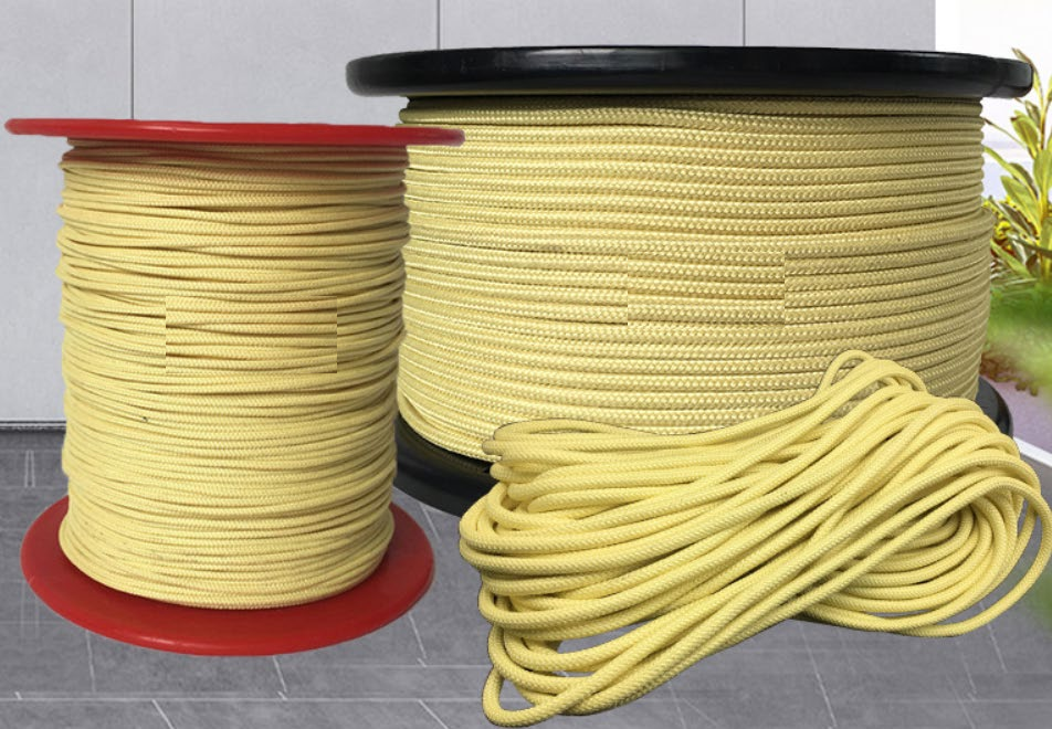 Figure 7-7 Kevlar guy-rope kit |
|---|
This section describes the safety conventions used throughout the manual and the precautions that must be observed during installation, operation and maintenance. Installation, operation and maintenance are to be carried out by trained and authorized personnel only.
|
DANGER Indicates an imminently hazardous situation which, if not avoided, will result in death or serious injury. |
|---|
|
WARNING Indicates a potentially hazardous situation which, if not avoided, could result in death or serious injury. |
|---|
|
CAUTION Indicates a potentially hazardous situation which, if not avoided, may result in minor or moderate injury. It is also used to alert against unsafe practices. |
|---|
The following precautions are not related to any specific procedure and therefore do not appear elsewhere in this manual. They must be understood and applied during all phases of operation and maintenance.
Electrocution hazard. Contact with high voltage will result in death or serious injury. Observe the general safety precautions for equipment using high voltage. Do not locate or operate the mast near electrical lines, cables or other sources of electricity. Do not operate the mast in lightning. Be certain that electrical cables are undamaged and properly terminated. Always disconnect power before performing service, repair or test work.
Read the manual. Failure to follow the operating instructions could result in death or serious injury. Read and understand this manual before using the mast.
Tip-over hazard. Mast tip-over could result in death or serious injury. Do not operate in high winds. Operate on level ground only. Stand clear of the mast and its payload during operation. Be certain that the mast is level and secure before and during installation, operation and maintenance.
Trained personnel only. Death or serious injury could result if the correct inspection, installation, operation and maintenance procedures are not observed. Only trained and authorized personnel may carry out this work. Wear eye protection when servicing the mast.
Health hazard. Solvents used to clean parts are potentially dangerous. Avoid inhalation of fumes and prolonged contact with the skin.
Resuscitation alert. Personnel working with or near high voltages should be familiar with modern methods of resuscitation.
The following precautions relate to specific procedures and are repeated at the relevant point in the text.
Pinch point hazard. Moving parts can crush and cut, resulting in death or serious injury. Keep clear of moving parts while operating the mast.
Crushing hazard. Death or serious injury could result if the mast fails suddenly. Do not stand directly beneath the mast or its payload. Be certain that the payload is properly installed and secured.
Relocation hazard. Relocating the mast during operation or after extension could result in death or serious injury. Do not relocate the mast during operation or while extended; this applies in particular to masts mounted on a trailer. Operate the mast only when the trailer is stationary and the vehicle engine is off.
Fire hazard. Do not smoke. Keep cleaning solvent away from ignition sources and always store it in a properly marked container.
Extension hazard. Extending the mast into obstructions could result in death or serious injury and could render the mast inoperable and partially extended. Before applying power, be certain that there is sufficient clearance above and to all sides of the fully extended mast and payload. Keep all persons clear and do not lean over the mast.
Pre-operation checks. Before any operation, confirm that the mast area is free of personnel and mechanical obstruction; that all electrical cables are undamaged and properly terminated; that the operator has a full view of the mast; that all transit tie-downs on the payload have been removed; that the vehicle is not moving; and that the area above the mast is free of obstructions.
Roof access. If the mast is mounted on a trailer, the user must provide a safe means of access to the trailer roof for installation and maintenance.
Entanglement hazard. Tangled cables can cause equipment damage. Ensure that control cables are not tangled and are free to pay out as the mast is extended.
|
Step |
Action |
|---|---|
|
1 |
Park the trailer on suitable ground. The ground must be firm, level and able to carry the full load of the tower and trailer. |
|
2 |
Using the spirit level, adjust the trailer platform to zero degrees on both the X and Y axes (see Figure 9-1 and Figure 9-2). |
|
3 |
Press the 90° tilt button on the touch-screen panel. The hydraulic power unit supplies oil to the cylinders and the tower moves to the vertical position. |
|
4 |
Fit the safety wheel thread bolt in the position shown in Figure 9-3. The bolt must actuate the switch sensor shown in Figure 9-4; until the sensor is made, the PLC will not permit elevation. |
Once the interlock is satisfied the tower rises section by section. Each section is locked in place by locking pins on all four sides until the tower reaches full height or a client-designated height.
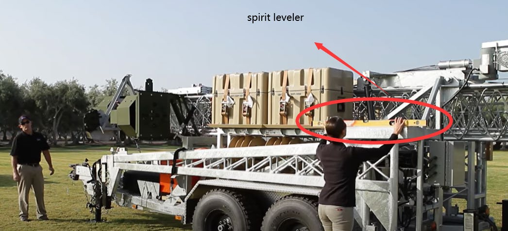
Figure 9-1 Trailer levelling and set-up on site
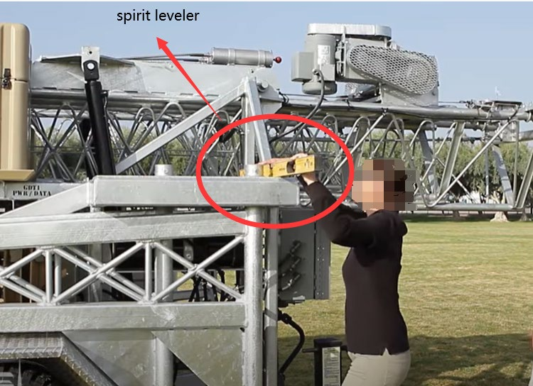
Figure 9-2 Spirit level reference on the platform
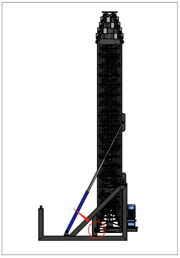
Figure 9-3 Safety wheel thread bolt position
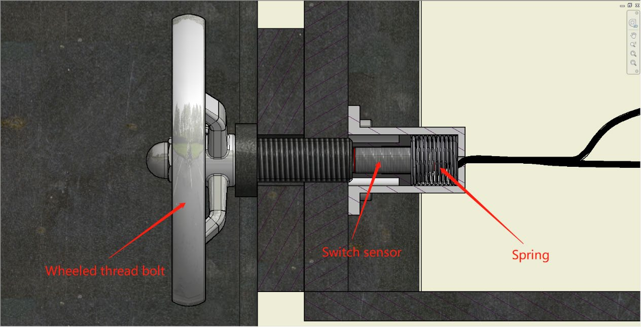
Figure 9-4 Switch sensor actuated by the safety wheel thread bolt
|
Step |
Action |
|---|---|
|
1 |
Keep all personnel clear of the area except the operator, and press the retract button on the touch-screen panel. The tower retracts one section at a time until the last section is fully retracted. |
|
2 |
Confirm that the last section is fully retracted, remove the safety wheel thread bolt, then press the tilt-down button. The tower lowers gradually to the horizontal position. |
For transport the tower is stowed horizontally on the trailer. The interface between the two items of equipment is defined below; the trailer itself is outside the scope of supply.
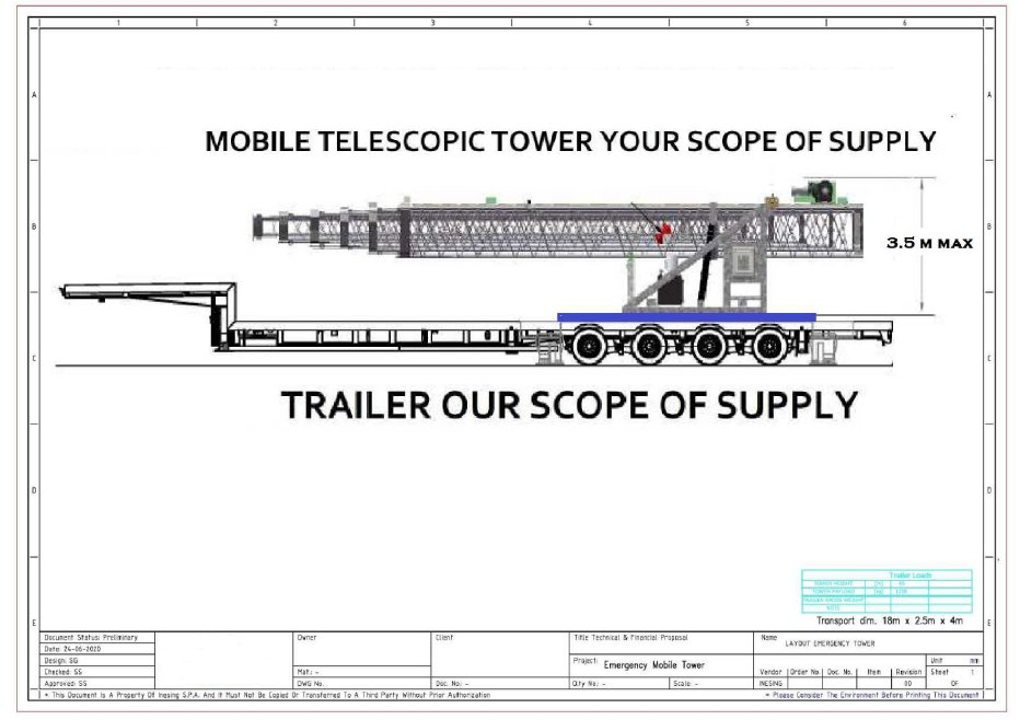
Figure 9-5 Transport configuration and scope interface
|
Item |
Scope of supply |
|---|---|
|
Mobile telescopic tower, including tilt frame, hydraulic system, PLC and control panel |
Homall Industry |
|
Trailer, including outriggers, running gear and lighting board |
Customer / trailer supplier |
Maximum transport envelope: 18 m × 2.5 m × 4 m. Overall height in the stowed condition 3.5 m.
The two source documents used to compile this manual reported different values for a number of parameters. The value adopted here, and the reason for the choice, are listed below. All values are to be confirmed against the contract-specific technical annex before manufacture.
|
Parameter |
Source 1 |
Source 2 |
Adopted |
Reason |
|---|---|---|---|---|
|
Face width, Sections 6 to 1 |
0.38 / 0.52 / 0.66 / 0.80 / 0.94 / 1.08 m |
0.40 / 0.54 / 0.68 / 0.82 / 0.96 / 1.10 m |
Source 2 |
Consistent 0.14 m taper per section; later revision |
|
Leg wall thickness, Sections 2 and 1 |
3 mm |
4 mm |
4 mm |
Higher load path in the base sections |
|
Mass, Sections 2 and 1 |
714 / 1,214 kg |
1,000 / 1,614 kg |
Source 2 |
Consistent with the 4 mm wall thickness |
|
Payload at top of tower |
1 t |
2.5 t |
2.5 t |
To be confirmed against the project load case |
|
Power requirement |
12 kW |
30 kW |
30 kW |
Source 2 value covers the system including the hydraulic unit |
|
Gear box ratio / motor speed |
1 : 10 / 1,400 r/min |
1 : 6.84 / 213 r/min |
Source 2 |
Consistent with the 22 kW belt drive |
|
Latch pin capacity |
3 t each, 6 t total |
6 t each, 12 t total |
Source 2 |
Source 1 contains an internal arithmetic inconsistency |
|
Motor rating |
12 kW |
22 kW in text, 30 kW in table |
22 kW motor, 30 kW system |
Distinction between motor rating and total system demand |
Editorial corrections made during consolidation: “Lightening protection” corrected to “Lightning protection”; units, spelling and hyphenation standardized to US English; section numbering, table formats and heading hierarchy unified across both source documents.
|
Field |
Detail |
|---|---|
|
Document number |
HI-TMS147-SM-01 |
|
Title |
TMS-147 45 m Telescopic Lattice Tower: General Specification & Operation Manual |
|
Revision |
1.0 |
|
Status |
Issued for customer review |
|
Date |
November 2026 |
|
Prepared by |
Homall Industry |
|
Supersedes |
TMS-147 product datasheet; TMS-147 general specification and operation manual |
|
Distribution |
Customer, project file |
Revision history
|
Rev. |
Date |
Description |
Prepared |
Approved |
|---|---|---|---|---|
|
1.0 |
Nov 2026 |
First issue. Consolidated from the two source documents; structure and typography unified; technical data reconciled. |
Homall Industry |
|
-