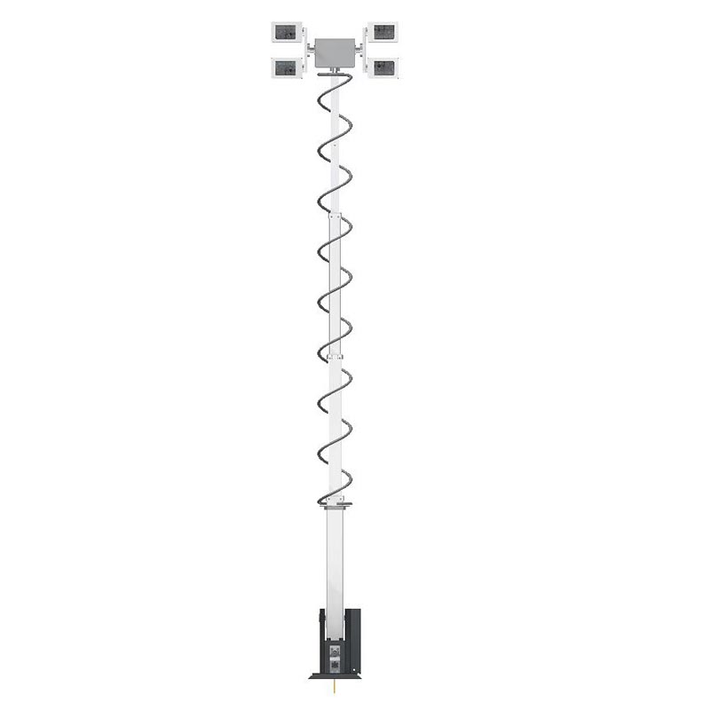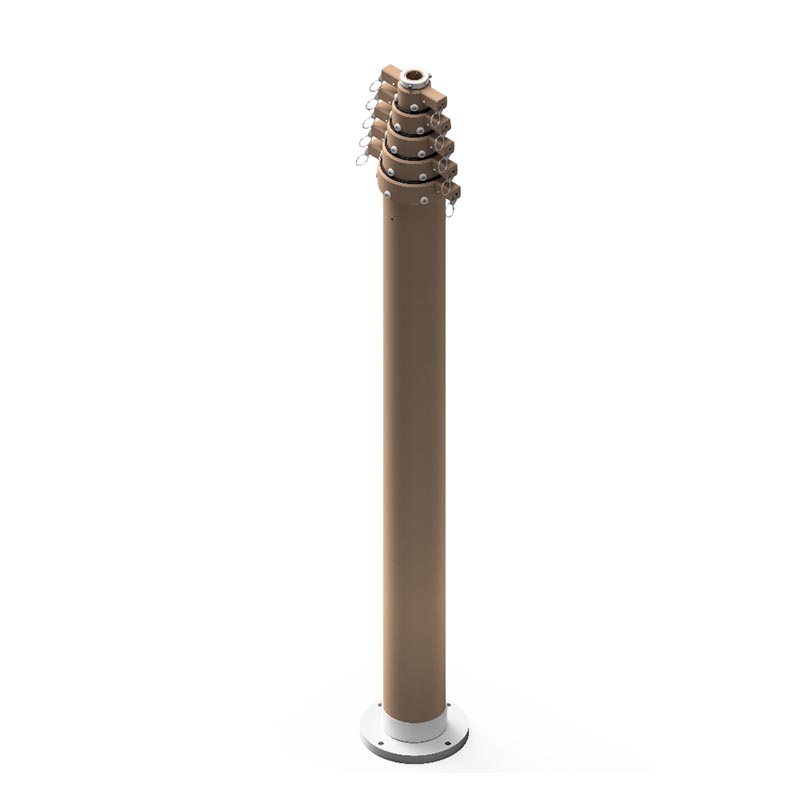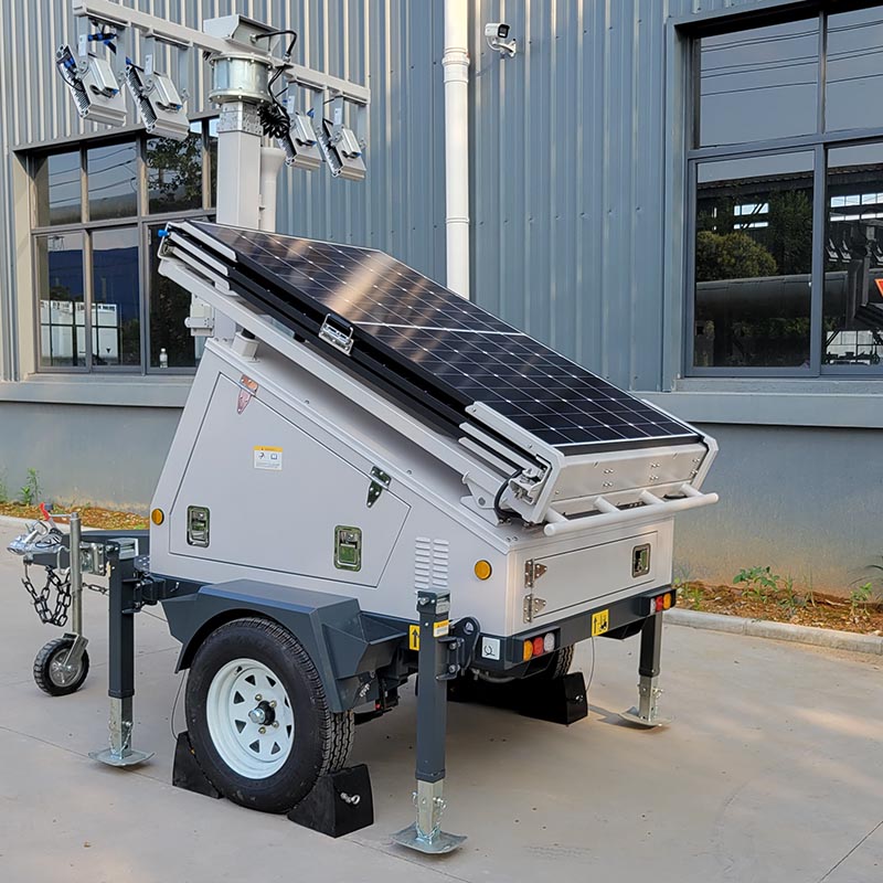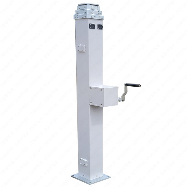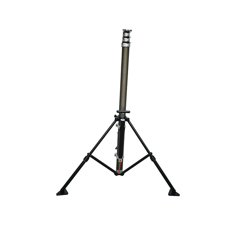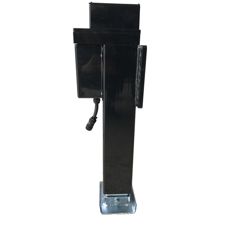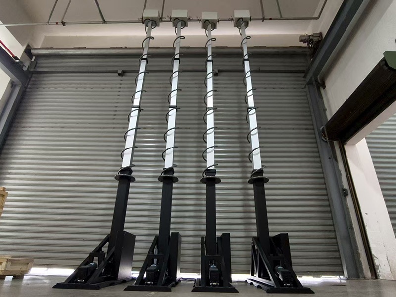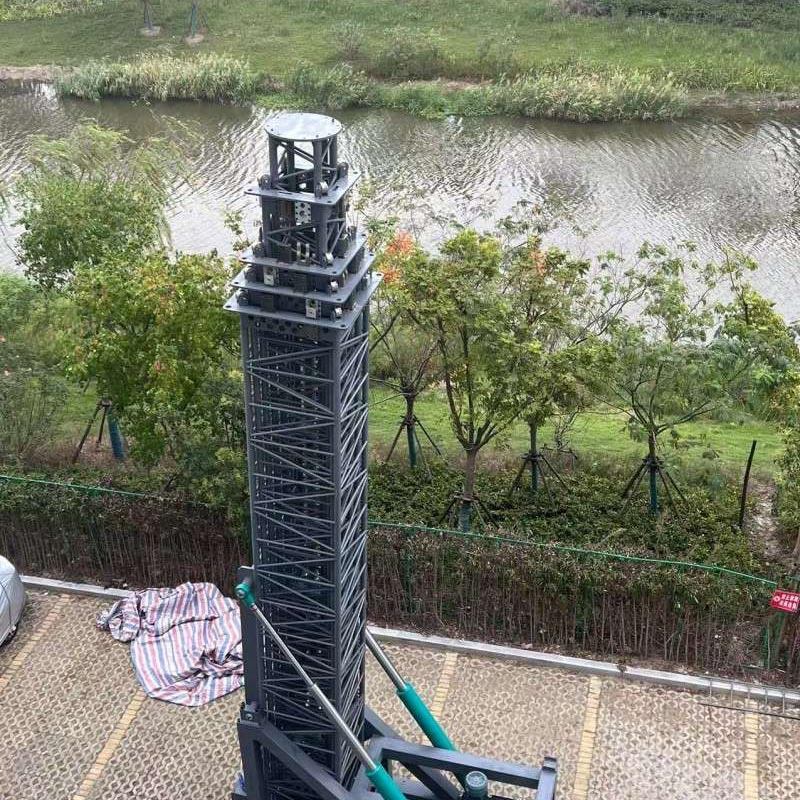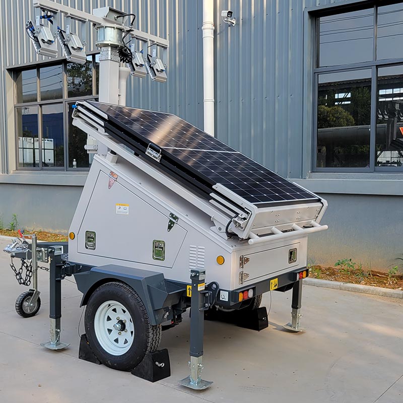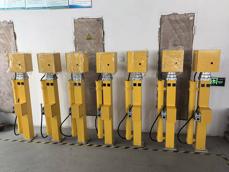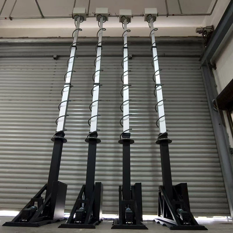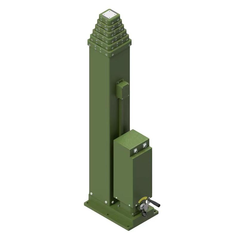

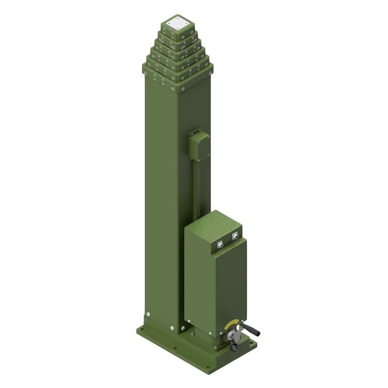
A spindle rope driven telescopic mast combines a compact multi-section mast structure with a mechanical lifting and retraction mechanism. This design can provide controlled height adjustment while helping equipment such as antennas, cameras, sensors, lighting systems and communication devices reach an elevated operating position without requiring a permanently tall structure.
Article Summary
A telescopic mast is designed to provide vertical extension when operating height is required and compact retraction when transportation, storage or low-profile operation is preferred. In a spindle rope driven configuration, the movement of nested mast sections is controlled through a mechanical drive arrangement involving a spindle, rope or cable routing, pulleys and associated structural components.
The main engineering challenge is not simply making a mast taller. A practical system must balance extended height, payload, stability, retracted length, operating speed, drive capacity, environmental exposure, section alignment and maintenance requirements. The right design therefore begins with the intended application rather than with mast height alone.
Table of Contents
- What the Spindle Rope Driven Design Means
- How the Mast Structure Works
- How the Drive Mechanism Operates
- Key Components and Their Functions
- Practical Advantages
- Common Engineering Challenges
- Key Specifications to Define
- Typical Applications
- Drive Technology Comparison
- Maintenance and Inspection
- Frequently Asked Questions
- Conclusion
Article Outline
What the Spindle Rope Driven Design Means
The phrase spindle rope driven telescopic mast describes a mast system in which telescoping sections are moved through a mechanically controlled drive arrangement. A telescopic mast normally consists of several nested sections. When the system is retracted, the sections fit inside one another to reduce the overall footprint. During deployment, the sections move progressively upward to create the required working height.
Rope-driven telescopic mechanisms commonly use a drive spool, pulleys and a routed cable or rope to transmit movement between mast sections. Research and engineering literature describes cable-driven telescopic mechanisms in which a drive spool takes up cable and the resulting cable movement causes the mast sections to extend. :contentReference[oaicite:1]{index=1}
A spindle-based mechanism introduces another mechanical element for controlled linear movement. Spindle systems can be designed for accurate positioning and controlled extension or retraction. Commercial mast systems also demonstrate the use of spindle-based and cable-driven approaches for different combinations of height and payload requirements. :contentReference[oaicite:2]{index=2}
How the Mast Structure Works
The basic structure consists of a fixed base section and multiple nested sections. Each section must move smoothly relative to the neighboring section while maintaining sufficient structural support for the equipment mounted at the top.
During retraction, the sections slide or move into the lower sections, reducing the overall mast height. During extension, the sections are progressively deployed until the required operating position is reached.
Section geometry is particularly important because the mast must resist unwanted movement while extended. Guides, sliding surfaces, mechanical interfaces and anti-rotation features can help control the relative movement of nested sections. Patent literature on telescopic mast structures identifies guides and distance-control elements as important for maintaining section alignment and limiting unwanted rotation. :contentReference[oaicite:3]{index=3}
Structural Factors That Matter
- Section length: Influences the overall extended height and retracted dimensions.
- Tube diameter: Affects structural stiffness, available internal space and equipment integration.
- Material: Aluminum and other engineered materials may be selected according to weight, strength and environmental requirements.
- Guidance system: Helps maintain smooth and predictable movement between sections.
- Anti-rotation design: Helps prevent unwanted rotation of equipment mounted at the top.
- Base structure: Transfers vertical and lateral forces into the installation platform.
How the Drive Mechanism Operates
The operating principle can be understood as a chain of mechanical movement. A motor or manual input drives the transmission system. The spindle or related drive component controls the movement, while the rope or cable transfers force to the telescopic sections through a carefully arranged routing system.
- Drive input begins. A motorized or manually operated drive supplies rotational movement to the mechanical transmission.
- The spindle or drive element rotates. Rotational motion is converted into controlled mechanical movement.
- The rope or cable transfers the movement. Routed through suitable pulleys and attachment points, the rope transmits force to the moving mast sections.
- The telescopic sections extend. Nested sections move progressively upward while guides maintain alignment.
- The desired height is reached. The control system or mechanical arrangement stops movement at the defined position.
- Retraction reverses the movement. The drive system releases or reverses the lifting mechanism so that the mast returns to its compact position.
Rope-driven systems can distribute movement across multiple telescopic sections using pulley arrangements. A documented portable telescopic mast design, for example, uses a motor-reducer group, pulleys, a drum and a drive rope to move nested sections using a single drive unit. :contentReference[oaicite:4]{index=4}
Key Components and Their Functions
| Component | Primary Function | Design Consideration |
|---|---|---|
| Mast Sections | Create the telescopic structure and working height. | Strength, stiffness, weight and section geometry. |
| Spindle / Drive Element | Converts rotational input into controlled mechanical movement. | Load capacity, precision, wear and transmission efficiency. |
| Rope or Cable | Transfers movement and lifting force between drive and mast sections. | Strength, flexibility, fatigue resistance and routing. |
| Pulleys | Change rope direction and support the transmission path. | Diameter, bearing quality, alignment and rope compatibility. |
| Guide System | Controls relative movement between sections. | Low friction, alignment and long-term wear resistance. |
| Locking System | Helps hold the mast in the required operating condition. | Load path, redundancy and environmental reliability. |
| Base / Mounting System | Connects the mast to a vehicle, platform or fixed installation. | Wind load, vibration, installation space and structural strength. |
Practical Advantages of a Spindle Rope Driven Telescopic Mast
1. Compact Storage
One of the biggest reasons to choose a telescopic mast is the difference between its operating height and retracted height. Instead of maintaining a permanently tall structure, the mast can remain compact when elevation is not required.
2. Controlled Deployment
A mechanical drive allows the extension process to be controlled rather than relying solely on manual lifting. This can be particularly useful when equipment is heavy, mounted at significant height or installed in locations where repeated deployment is required.
3. Flexible Equipment Integration
Telescopic masts can serve as elevated mounting platforms for different equipment. Depending on the structural design and rated payload, possible applications include antennas, cameras, sensors, lighting equipment, monitoring devices and other technical systems.
4. Adjustable Operating Height
The ability to change mast height can help operators adapt equipment positioning to different operating conditions. A monitoring camera, for example, may require one height during normal operation and a lower position during transport or maintenance.
5. Efficient Use of Installation Space
A retractable mast can be useful where permanent tower structures are impractical. Vehicle-mounted systems, temporary field equipment and compact monitoring installations can benefit from a structure that occupies less vertical space when not deployed.
Common Engineering Challenges
A telescopic mast must perform as a complete mechanical system. Increasing the mast height without considering the load path, wind conditions and drive mechanism can create performance problems.
Payload and Center of Gravity
The rated payload should include the equipment mounted at the top as well as any relevant mounting hardware. The location of the payload also matters because an elevated or offset load can increase the bending moment on the mast.
Wind and Lateral Loading
Wind can become a major factor as mast height increases. The antenna, camera, light or sensor mounted at the top also presents an exposed area. Therefore, structural design should consider both vertical payload and lateral environmental loads.
Rope Fatigue and Wear
Rope-driven mechanisms are repeatedly subjected to bending around pulleys and tension changes. Proper rope selection, pulley geometry, routing and inspection are therefore important for long-term operation.
Section Alignment
Poor alignment can increase friction and create uneven loading. Guide surfaces and section interfaces should be designed to maintain controlled movement throughout repeated extension and retraction cycles.
Environmental Exposure
Outdoor installations can encounter rain, dust, temperature changes, salt exposure, vibration and other environmental conditions. These factors should be considered when selecting materials, bearings, protective finishes, seals and maintenance procedures.
Key Specifications to Define Before Ordering
The most common purchasing mistake is asking only for “a telescopic mast of a certain height.” A more complete specification helps the manufacturer develop a configuration that matches the actual operating environment.
| Specification | Why It Matters | Information to Prepare |
|---|---|---|
| Extended Height | Defines the required working elevation. | Target height in meters or feet. |
| Retracted Height | Determines transportation and installation constraints. | Maximum allowable packed height. |
| Payload | Determines structural and drive requirements. | Equipment weight plus mounting hardware. |
| Wind Condition | Influences mast stability and structural loading. | Site or operating wind requirements. |
| Deployment Frequency | Affects component life and maintenance planning. | Cycles per day, week or month. |
| Installation Method | Determines base and support design. | Vehicle, trailer, building, ground or platform. |
| Power Supply | Determines motor and control compatibility. | Voltage, AC/DC source and available power. |
| Operating Environment | Affects materials and protective measures. | Indoor/outdoor, temperature, dust, moisture and corrosion conditions. |
Where Spindle Rope Driven Telescopic Masts Can Be Used
Communication Equipment
Telescopic masts can elevate antennas and communication equipment to improve positioning and coverage. A retractable structure can also simplify transportation between operating locations.
Security and Monitoring
Cameras and other monitoring equipment may need to be elevated to obtain a wider field of view. A retractable mast provides a way to raise equipment during operation and lower it for maintenance or transport.
Lighting Systems
Temporary or mobile lighting equipment can be mounted on an extendable structure where elevated positioning is required. The actual payload and wind rating should be verified before selecting the mast.
Environmental and Industrial Sensors
Sensors may require a specific elevation to collect useful measurements. A telescopic mast can provide adjustable positioning while keeping the overall installation relatively compact.
Mobile and Field Equipment
Vehicle-mounted and portable systems can use telescopic structures when equipment must be deployed at different locations. Existing mast designs are used in both stationary and mobile applications, including vehicle and ship-mounted configurations. :contentReference[oaicite:5]{index=5}
Spindle Rope Driven vs. Other Mast Drive Approaches
Different mast drive systems solve different engineering problems. The appropriate technology depends on the required height, payload, deployment frequency, positioning requirements and installation environment.
| Drive Approach | Typical Characteristics | Potential Strength | Important Consideration |
|---|---|---|---|
| Spindle Driven | Mechanical screw/spindle movement controls mast sections. | Controlled and repeatable movement. | Spindle length, load and mechanical complexity. |
| Rope / Cable Driven | Rope and pulley arrangements transmit lifting movement. | Flexible routing and compact drive arrangements. | Rope wear, pulley alignment and tension. |
| Pneumatic | Compressed air or gas provides extension force. | Can offer rapid deployment for suitable applications. | Air supply, pressure management and application-specific control. |
| Manual Crank | Operator supplies mechanical input. | Simple power requirements. | Operator effort and deployment speed. |
Commercial telescopic mast ranges demonstrate that cable-driven, spindle-driven and pneumatic technologies can each occupy different application areas, with available height and payload varying substantially between product families. :contentReference[oaicite:6]{index=6}
Maintenance and Inspection Checklist
Regular inspection is particularly important for a mast that is repeatedly extended and retracted. Maintenance should follow the manufacturer's instructions and the actual operating environment.
- Inspect the rope or cable for visible wear, damage, deformation or abnormal tension.
- Check pulleys and bearings for unusual noise, resistance or misalignment.
- Inspect mast section interfaces and guide surfaces for excessive wear.
- Check fasteners, mounting points and structural connections.
- Verify that the locking or holding mechanism operates correctly.
- Keep sliding and mechanical components maintained according to the manufacturer's lubrication requirements.
- Inspect for corrosion, contamination or damage after severe outdoor exposure.
- Monitor unusual vibration, uneven extension or changes in operating speed.
- Do not exceed the specified payload or environmental operating limits.
Frequently Asked Questions
What is a spindle rope driven telescopic mast?
It is a telescopic mast that uses a mechanical drive arrangement incorporating a spindle and rope or cable transmission to extend and retract nested mast sections. The exact mechanical configuration varies by manufacturer and application.
What equipment can be mounted on a telescopic mast?
Depending on the rated payload and structural design, equipment may include antennas, cameras, sensors, lighting equipment, communication devices and industrial monitoring systems. The equipment weight and wind-exposed area should be considered during mast selection.
Why is retracted height important?
Retracted height determines how easily the mast can be transported, stored or installed. For vehicle-mounted applications, it may also affect the overall vehicle clearance and available installation space.
Does a taller mast always provide better performance?
Not necessarily. Greater height can increase useful elevation, but it can also increase structural demands, wind loading, drive requirements and stability considerations. The target height should therefore be matched to the actual application.
Can a telescopic mast be customized?
Telescopic mast systems can be engineered around application-specific requirements such as extended height, retracted height, payload, mounting method, power supply, section configuration and environmental conditions. Customization should be confirmed against the manufacturer's engineering capabilities.
What information should buyers provide to a manufacturer?
Buyers should ideally provide required extended and retracted height, payload, equipment dimensions, center of gravity, wind conditions, deployment frequency, mounting method, power supply and operating environment. More complete application information helps reduce specification mismatches.
How is a spindle driven mast different from a conventional rope driven mast?
A conventional rope-driven mast primarily relies on rope and pulley transmission, while a spindle-driven arrangement uses a mechanical spindle to create controlled movement. Some systems can combine different mechanical elements, so the actual design should be evaluated from its complete drive architecture rather than from the product name alone.
Conclusion: Building the Right Telescopic Mast for the Application
A spindle rope driven telescopic mast is more than a set of nested tubes with a lifting mechanism. Its performance depends on the interaction between structural sections, drive components, rope routing, guides, mounting points, locking arrangements and the equipment carried at the top.
For buyers, the most useful starting point is to define the application in practical terms: how high the equipment needs to be, how compact the mast must become, what payload it will carry, how often it will operate and what environmental conditions it will encounter.
For manufacturers and engineering teams, these requirements provide the foundation for selecting the appropriate section configuration, transmission arrangement, materials, drive capacity and mounting solution. A well-matched system can provide controlled deployment while keeping the structure practical for transportation, installation and repeated operation.
Need a Telescopic Mast for a Specific Application?
Homall Industry Limited can help customers evaluate telescopic mast requirements based on application height, payload, installation conditions and operating needs. If you are developing a communication, monitoring, lighting, sensing or mobile deployment system, contact us to discuss the required configuration and technical specifications.